Our Location
Killa-Pardi, Dist. Valsad, 396125

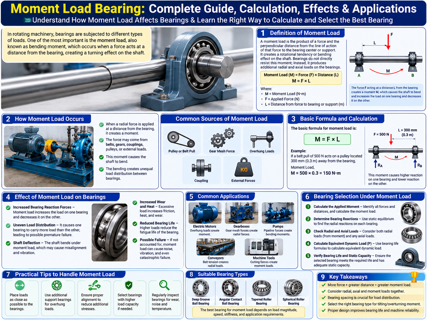
In rotating machinery, bearings are used to support shafts and allow smooth, controlled rotation. Depending on the machine design, a bearing may experience radial load, axial load, or a combination of radial, axial, and moment loads. Among these, moment loading is especially important when a force acts at a distance from the bearing support.
A moment load bearing refers to a bearing or bearing arrangement that must resist the effects of a bending or tilting moment created by an external force. This situation is common in machines with overhung pulleys, gears, fans, couplings, rollers, cutting tools, and other components mounted away from the bearing support.
Understanding what is moment load in bearing, how a bearing handles moment load, how to calculate bearing reactions, and how to select a suitable bearing for moment load is essential for reliable machine design.
A moment load in bearing occurs when a force acts at some distance from the center of a bearing or bearing support. Instead of producing only a direct radial or axial force, the offset force creates a tendency to bend or rotate the shaft.
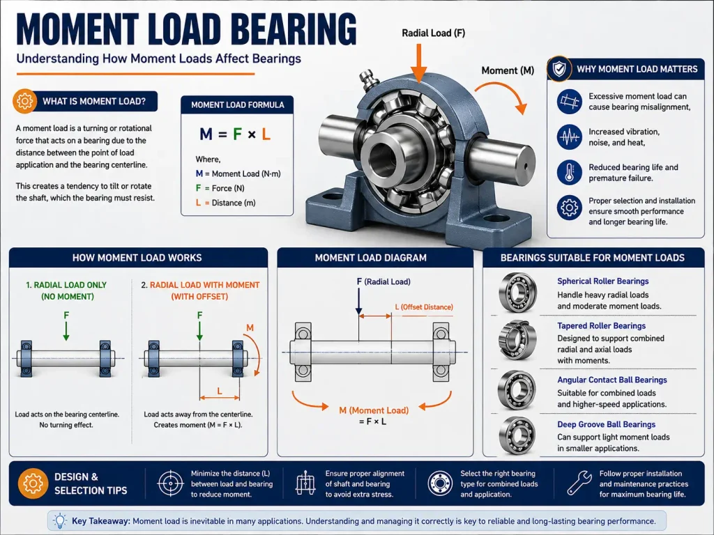
For example, imagine a shaft supported by two bearings with a heavy pulley mounted outside one bearing. The pulley weight and belt tension act away from the bearing. These forces create a bending or tilting effect on the shaft.
This is commonly called a tilting moment, bending moment, or, in certain machine arrangements, an overturning moment.
In simple terms:
A moment load is the turning or bending effect created when a force acts at a distance from a support.
A bearing arrangement does not simply carry the moment as one isolated force. Instead, the moment creates reaction forces at the bearing locations. One bearing may carry more load than the other depending on the position of the external force and the distance between the bearings.
This is why analyzing a bearing subjected to moment load requires consideration of the complete shaft and bearing arrangement.
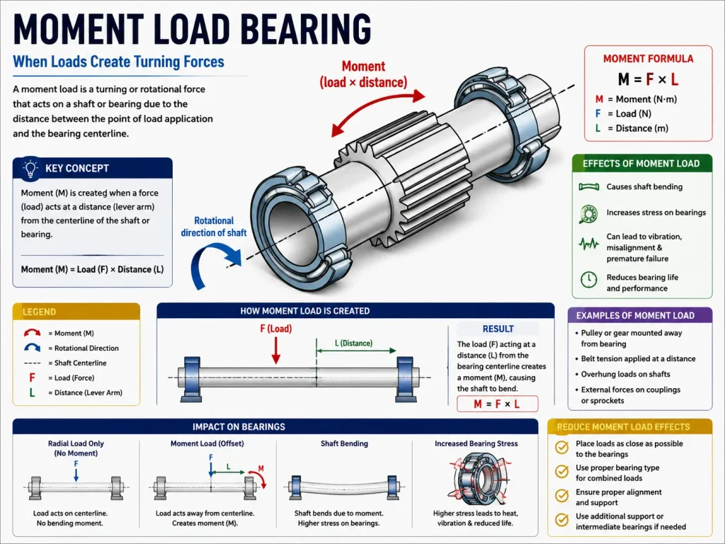
The simplest bearing moment load formula is:
M = F × L
Where:
M = Moment load
F = Applied force
L = Perpendicular distance between the force and bearing support
Example Of How To Calculate Moment Load :
Suppose a 500 N force acts at a distance of 300 mm from a bearing.
First convert the distance:
300 mm = 0.3 m
Now:
M = F × L
M = 500 × 0.3
M = 150 N·m
Therefore, the resulting moment load is:
150 N·m
Now suppose the same 500 N force acts at 600 mm:
M = 500 × 0.6
M = 300 N·m
The moment has doubled simply because the distance doubled. This is one of the most important principles in moment load calculation for bearing:
For the same force, increasing the distance increases the moment directly.
A common engineering question is: How does a bearing handle moment load?
The answer depends on the bearing type, bearing arrangement, shaft geometry, and distance between the supporting bearings.
Consider a shaft supported by two bearings, A and B. If an external force acts away from the center of the bearing arrangement, the force creates a moment.
The bearing reactions must satisfy the basic equilibrium conditions:
ΣF = 0 and ΣM = 0
The reactions developed at the two bearings resist the bending effect.
Depending on the location of the external force, one bearing may experience a much greater reaction than the other.
Therefore, simply knowing the external force is not enough. Engineers must determine:
This is particularly important in bearing under moment loading because the actual load on an individual bearing can be significantly different from the original external force.
Moment loads occur in many types of industrial machinery.
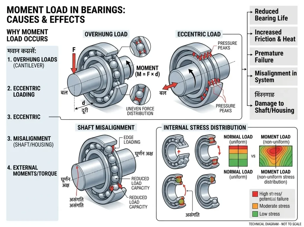
An overhung load occurs when a component such as a pulley, fan, gear, or coupling is positioned outside the main bearing support.
Because the component is separated from the bearing, its force produces a bending moment.
The basic relationship remains:
M = F × L
The greater the overhang distance, the greater the moment.
Belt-driven systems generate radial forces through belt tension. If the pulley is mounted away from the bearing, the belt force creates a moment on the shaft.
This is common in:
Gears can generate radial and axial forces. Depending on gear position, these forces can produce significant bending moments.
Helical gears can additionally generate axial thrust.
A poorly aligned coupling can introduce additional radial and axial forces. If the coupling is positioned away from the bearing, these forces can create additional moments.
Cutting tools, rollers, impellers, fans, and other rotating components can apply forces at a distance from the bearing support.
Real machines often operate under combined radial axial and moment load conditions.
A gearbox may therefore experience all three:
This means choosing a bearing for combined load requires more than checking the radial load rating.
The bearing must be evaluated for radial load, axial load, moment loading, speed, stiffness, lubrication, and required service life.
A tilting moment bearing is generally associated with an application where an external moment attempts to tilt the shaft or bearing assembly. A tilting moment can produce uneven contact loading within the bearing arrangement.
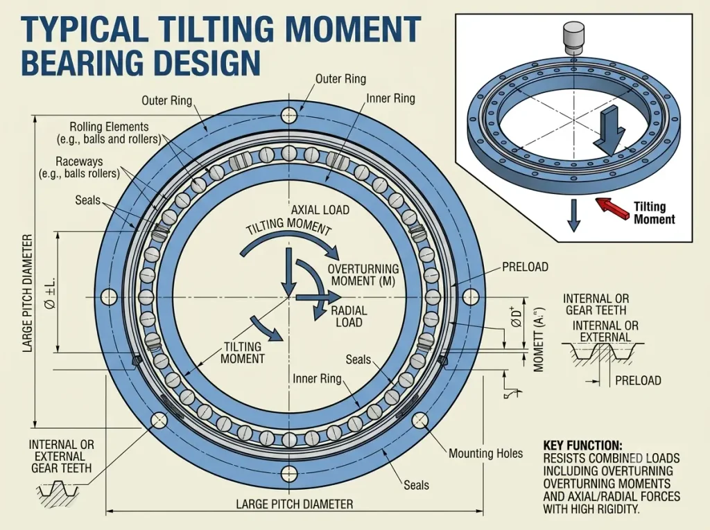
For example, an overhung fan mounted on a shaft may create a moment that causes the shaft to bend. This bending can change the alignment between the shaft and bearing.
A bearing for tilting moment should therefore be selected by considering:
For significant moment loading, bearing arrangement can be as important as the bearing itself.
An overturning moment bearing is relevant when an external force attempts to rotate a machine component around a support. This type of loading is common in:
For example, if a heavy machine component applies a force at a considerable distance from its support, the resulting overturning moment can be large.
The calculation starts with:
M = F × L
When selecting a bearing for overturning moment, the engineer must determine how the moment is transferred through the complete bearing arrangement.
Excessive moment loading can produce several problems.
Therefore, bearing subjected to moment load conditions must be evaluated carefully.
Bearing moment capacity describes the ability of a bearing arrangement to withstand an applied moment while maintaining acceptable loading, deformation, stiffness, and service life. It is important to understand that there is not necessarily one universal moment-capacity value for every bearing.
The effective bearing moment load capacity depends on:
Therefore, bearing capacity for moment load should be evaluated using the manufacturer’s technical data and the actual machine geometry.
A common question is how to calculate bearing moment capacity.
The first step is to calculate the applied moment: M = F × L
Next, determine the reactions at the bearings using static equilibrium.
For a simplified two-bearing arrangement, the moment-related reaction can be approximated using:
Reaction ≈ M / Bearing Span
Suppose:
Then:
Reaction ≈ 600 / 0.6
Reaction ≈ 1,000 N
This is a simplified engineering relationship. Actual reactions depend on the complete shaft geometry and all applied forces. After calculating the bearing reactions, the engineer determines the appropriate equivalent dynamic and static bearing loads.
Therefore, bearing moment load calculation is a multi-step process rather than simply calculating M = F × L.
A practical moment load calculation for bearing can be performed as follows.
| Step 1: Identify All Forces | List every important force: Radial forces Axial forces Belt tension Gear forces Component weights Coupling forces External machine forces |
| Step 2: Identify Force Locations | Determine the perpendicular distance from each force to the bearing or support. |
| Step 3: Calculate Each Moment | Use: M = F × L Calculate each moment separately. |
| Step 4: Apply Equilibrium Equations | Use: ΣF = 0 and ΣM = 0 to determine the reactions at the bearing locations. |
| Step 5: Determine Combined Bearing Load | Combine the resulting radial and axial loads using the appropriate bearing manufacturer’s equations. |
| Step 6: Check Dynamic Load Capacity | Compare the calculated equivalent dynamic load with the bearing’s dynamic load rating. |
| Step 7: Check Static Capacity | Check the maximum static or shock loading against the bearing’s static load rating. |
| Step 8: Check Bearing Life | Calculate the expected fatigue life using the appropriate bearing-life equation. |
Different bearing types have different capabilities.
The best bearing for moment load therefore depends on the actual loading and machine configuration.
Bearing selection for moment load should consider the complete operating condition rather than only the bearing bore. Important parameters include:
There is no single answer to which bearing is best for moment load.
For moderate loading, an appropriately selected deep-groove or angular-contact ball bearing may be sufficient.
For applications with significant combined radial and axial loads, tapered roller or angular-contact arrangements may be more appropriate.
For higher tilting moments, double-row bearings or properly arranged bearing pairs can provide greater resistance.
The selection should be based on:
Moment + Radial Load + Axial Load + Speed + Stiffness + Bearing Life + Mounting Arrangement
Therefore, a high moment load bearing should not be selected simply because it has a high radial load rating.
Bearing spacing is one of the most important factors in a moment-loaded shaft. Consider two bearings supporting a shaft. If the bearings are very close together, a large reaction may be required to resist a given moment. Increasing the bearing span can reduce the reaction associated with the moment.
A simplified relationship is:
Reaction = Moment / Bearing Span
For example:
Moment = 400 N·m
Bearing span = 0.8 m
Therefore:
Reaction ≈ 400 / 0.8 = 500 N
This is only a simplified calculation. A complete shaft analysis should include all external forces and support conditions.
Nevertheless, it clearly demonstrates why bearing spacing matters in bearing moment capacity.
Moment loading occurs in many industrial applications.
| Electric Motors | Overhung pulleys, fans, and couplings can generate bending moments on motor shafts. |
| Gearboxes | Gear forces can generate radial, axial, and moment loading. |
| Pumps | Pump shafts can experience loads from impellers, couplings, seals, and connected components. |
| Conveyors | Drive pulleys and conveyor rollers can generate radial and bending loads. |
| Fans | Large fans mounted away from their bearing supports can create significant overhung moments. |
| Machine Tools | Cutting forces may act away from the bearing support and create a bending moment. |
| Industrial Robots | Robot joints can experience combined radial, axial, and overturning moments. |
| Heavy Machinery | Large components and eccentric loads can create substantial overturning moments. |
Several design strategies can reduce moment loading.
Early detection can prevent expensive machine failure.
| Mistake 1: Ignoring Force Distance | A common mistake is calculating only the force and ignoring the distance from the bearing. |
| Mistake 2: Treating Moment as Simple Radial Load | A moment changes the distribution of loads between bearings. It should not automatically be treated as one simple radial force. |
| Mistake 3: Ignoring Bearing Spacing | Bearing spacing affects the reaction forces generated by the moment. |
| Mistake 4: Selecting Only by Bore Size | A bearing should not be selected only because its bore matches the shaft diameter. |
| Mistake 5: Ignoring Static Capacity | A bearing may have sufficient calculated dynamic life but still suffer damage from excessive stationary or shock loading. |
| Mistake 6: Ignoring Speed | Load capacity must be considered together with rotational speed and lubrication. |
| Mistake 7: Ignoring Misalignment | Shaft deflection or installation errors can introduce additional forces. |
| Mistake 8: Using Incorrect X and Y Factors | For combined radial and axial loads, the correct load factors depend on the specific bearing design and manufacturer. |
Bearing static moment capacity is particularly important when the machine is stationary or exposed to heavy impact and shock loads. Dynamic capacity is mainly related to bearing fatigue life during rotation.
Both should be checked.
A complete analysis should consider:
Ignoring static capacity can result in permanent deformation even if the calculated fatigue life appears satisfactory.
Consider a shaft supported by two bearings.
Given:
| Step 1: Calculate Moment | M = F × L M = 1,000 × 0.4 M = 400 N·m |
| Step 2: Determine Bearing Reactions | The 400 N·m moment and 1,000 N external force are used with the shaft geometry to calculate the reactions at the two bearings. |
| Step 3: Consider Axial Load | The 400 N axial load must also be included when determining the appropriate equivalent bearing load. |
| Step 4: Check Dynamic Capacity | Compare the resulting equivalent dynamic load with the manufacturer’s dynamic load rating. |
| Step 5: Check Static Capacity | Check maximum operating and shock loads against the static rating. |
| Step 6: Check Life | Use the appropriate bearing-life calculation to determine whether the selected bearing can meet the required service life. |
This example demonstrates that moment load bearing capacity calculation requires both the applied moment and the resulting bearing reactions.
The following factors have the greatest influence on bearing moment load capacity:
| Force | Increasing force increases the moment |
| Distance | Increasing the force’s distance from the support increases the moment |
| BearingSpan | Increasing support spacing can reduce moment-related reaction forces |
| Bearing Type | Different bearing geometries provide different load and stiffness characteristics |
| Shaft Stiffness | A flexible shaft can increase deflection and misalignment |
| Speed | Higher speed changes thermal and lubrication requirements |
| Lubrication | Poor lubrication can increase friction and temperature |
| Alignment | Misalignment can introduce additional loading |
| Static Capacity | Shock and stationary loading must be checked |
| Dynamic Capacity | Fatigue life must be verified |
A moment load bearing handles an external force acting at a distance from the bearing support, creating a bending or tilting effect.
The basic formula is: M = F × L
Where M = moment load, F = applied force, and L = distance from the bearing.
For a complete bearing moment load calculation, engineers should consider bearing reactions, radial and axial loads, bearing spacing, shaft stiffness, alignment, static and dynamic capacity, and bearing life.
Moment loads are common in motors, gearboxes, pumps, conveyors, fans, and machine tools, especially with overhung components.
Key principle: Greater force or greater distance from the bearing creates a higher moment load. Proper bearing selection, spacing, alignment, and load calculation help reduce vibration, wear, and premature failure.
Moment load is the bending or tilting effect created when a force acts at a distance from the bearing support.
A moment load bearing is a bearing or bearing arrangement designed or selected to support the effects of an applied bending or tilting moment.
The basic formula is:
M = F × L
where M is moment, F is force, and L is the perpendicular distance from the support.
First calculate each force multiplied by its perpendicular distance from the support. Then use static equilibrium equations to determine the reaction at each bearing.
Calculate the applied moment, determine bearing reactions, calculate the resulting equivalent bearing loads, and compare them with the manufacturer’s dynamic and static ratings.
There is no universal best bearing. Angular-contact, double-row, tapered roller, or properly paired bearing arrangements may be suitable depending on the magnitude and direction of the loads.
Yes. A radial force creates a moment when it acts at a distance from the bearing support.
It refers to a bearing or bearing arrangement subjected to a moment that attempts to tilt the shaft or bearing assembly.
It is a bearing arrangement used in applications where an external force creates a moment that attempts to rotate or overturn a machine component around its support.
It is the ability of a bearing arrangement to withstand an applied moment while maintaining acceptable stress, deformation, stiffness, and service life.
It is a condition where a bearing simultaneously experiences radial force, axial force, and a bending or tilting moment.
Moment load can be reduced by decreasing the external force, reducing overhang distance, increasing bearing spacing where practical, improving alignment, increasing shaft stiffness, and selecting an appropriate bearing arrangement.
Bearing spacing affects the reaction forces required to resist a moment. Greater support spacing can often reduce moment-related reactions, depending on the complete shaft design.
Static capacity is important because stationary, shock, or impact loading can cause permanent bearing deformation even when calculated dynamic fatigue life is adequate.
A radial load acts directly perpendicular to the shaft axis, while a moment load represents a turning or bending effect created when a force acts at a distance from the support.

Welcome! I am a dedicated entrepreneur running an industrial affiliate product website, helping businesses and professionals find the best tools, equipment, and resources for their needs. With a passion for industrial products and a keen eye for quality, I curate and recommend top-performing items that enhance efficiency and reliability.
Through my platform, I aim to simplify the buying process by providing valuable insights, expert reviews, and trusted affiliate links to high-quality industrial products. Whether you’re looking for the latest machinery, tools, or safety gear, I strive to connect you with the best solutions available.
Thank you for visiting, and I look forward to helping you make informed purchasing decisions!
