Our Location
Killa-Pardi, Dist. Valsad, 396125

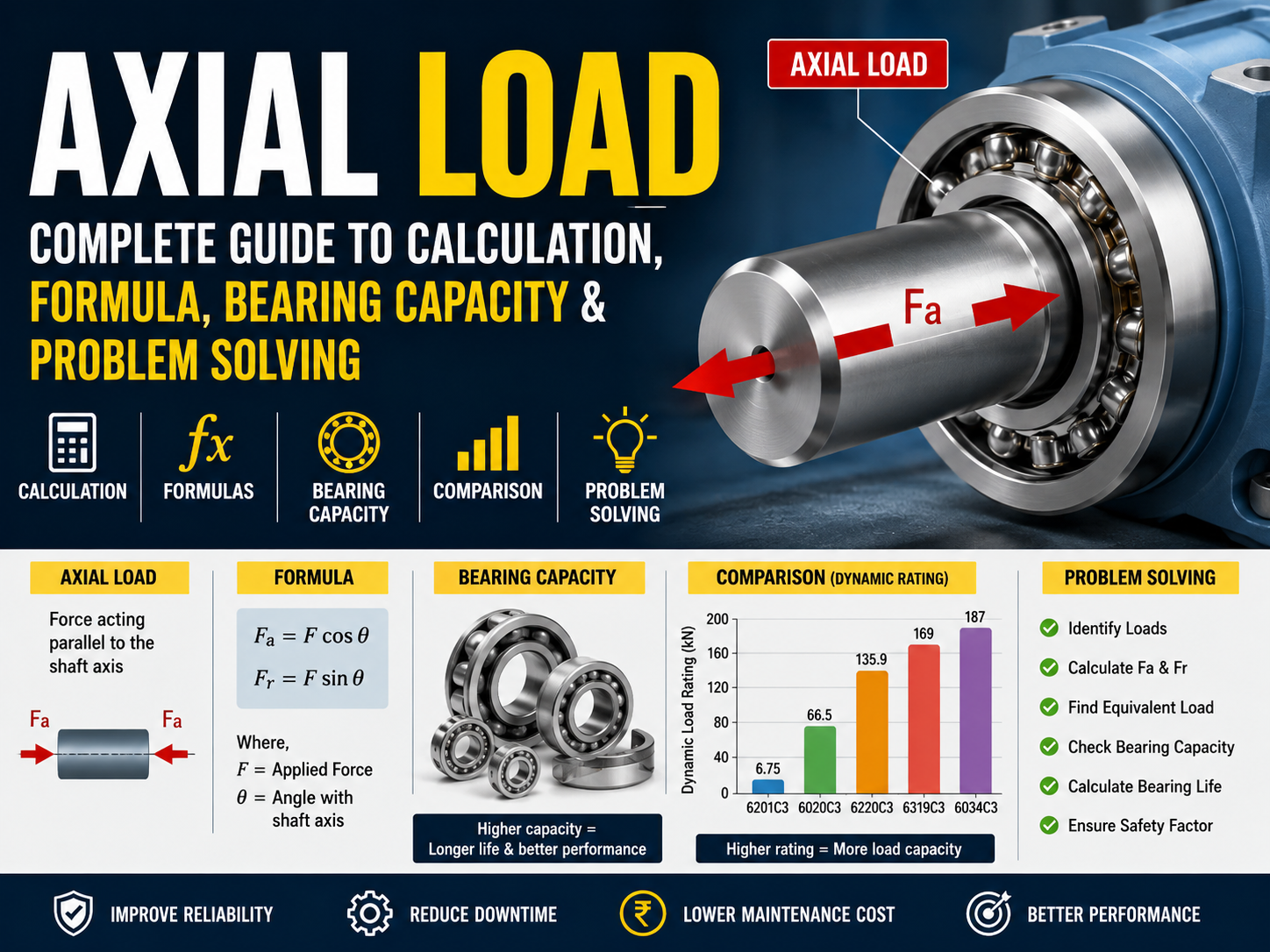
Axial load is one of the most important forces engineers must understand when designing shafts, bearings, gearboxes, pumps, motors, conveyors and rotating machinery.
An axial load acts parallel to the shaft or component’s axis. It is also commonly called thrust load or axial force.
For example, imagine a rotating shaft carrying a propeller. If the propeller pushes the shaft forward or backward, the resulting force along the shaft is an axial load. Similarly, a screw jack, ball screw, pump shaft, gearbox or vertical rotating shaft can experience significant axial forces.
Understanding axial force is essential because excessive thrust can cause:
A correct axial-load calculation therefore helps engineers select the correct bearing, shaft diameter, housing, lubrication system and safety factor.
According to SKF technical guidance, when a radial bearing is subjected to both radial and axial forces, the actual forces generally need to be converted into an equivalent dynamic bearing load before bearing life calculations are performed.
An axial load is a force that acts parallel to the longitudinal axis of a component.
For a shaft:
Axial Load = Force acting along the shaft axis
It is usually represented by:
Fa = Axial Load
where:
For example:
If a shaft experiences a force of 2,000 N along its axis:
Fa = 2,000 N = 2 kN
Consider a horizontal shaft:
← 2 kN | SHAFT | 2 kN →
The forces act along the shaft’s centerline. Therefore, they are axial forces.
Axial load is different from radial load.
The easiest way to understand the difference (Axial Load vs Radial Load) is by looking at the direction of force.
| Parameter | Axial Load | Radial Force |
|---|---|---|
| Direction | Parallel to shaft | Perpendicular to shaft |
| Common name | Thrust load | Radial force |
| Symbol | Fa | Fr |
| Main bearing type | Thrust bearing | Radial bearing |
| Example | Propeller thrust | Pulley belt load |
| Main effect | Shaft movement along axis | Shaft bending/displacement |
| Typical applications | Pumps, screws, gearboxes | Motors, conveyors, rollers |
Many real machines experience both forces at the same time.
SKF describes combined loading using the general equivalent-load relationship:
P = XFr + YFa
where P is the equivalent dynamic bearing load and X and Y are bearing-specific load factors.
For a simple mechanical system, the basic axial-load relationship is:
Fa = F
where the applied force is directly aligned with the axis.
For an inclined force:
Fa = F cos θ
and the radial component becomes:
Fr = F sin θ
where:
Suppose:
F = 10 kN
and the force acts at:
θ = 30°
Then:
Fa = 10 × cos 30°
Fa ≈ 8.66 kN
The radial component is:
Fr = 10 × sin 30°
Fr = 5 kN
Therefore, the original 10 kN force produces approximately:
This type of force decomposition is extremely useful when analyzing gears, belt drives, screw mechanisms and angled shafts.
Bearings are particularly important in axial-load applications.
A bearing may experience:
A thrust bearing is specifically designed to support axial loads.
Examples include:
SKF states that for a thrust bearing designed to carry purely axial, centrally applied load, the equivalent dynamic load can be simplified to:
P = Fa
However, a radial bearing subjected to combined loading requires the appropriate bearing-specific factors.
Axial load capacity means the maximum axial force that a bearing or mechanical component can safely support under specified conditions.
It is important to distinguish between:
The static load rating is associated with stationary or very slow-moving loading and permanent deformation considerations.
The dynamic load rating is used for bearing-life calculations under rotation.
For example, NTN lists a 6201C3 deep-groove ball bearing with a radial dynamic load rating of approximately 6.75 kN and static load rating of approximately 2.76 kN in its published specifications.
A larger NTN 6220C3 bearing is listed with approximately 135.9 kN dynamic rating and 93 kN static rating.
These examples demonstrate an important engineering principle:
Bearing capacity depends strongly on bearing size, internal geometry, bearing type and operating conditions.
Never assume that the axial capacity of one bearing can be determined simply from its radial dynamic rating.
One of the most important calculations is bearing life.
The basic ISO-style bearing life equation is:
L10 = (C/P)^p
where:
SKF documentation identifies the same basic relationship for bearing-life calculations.
Suppose a ball bearing has:
C = 20 kN
and the equivalent load is:
P = 5 kN
Then:
L10 = (20/5)^3
L10 = 4³
L10 = 64 million revolutions
Therefore, the basic rating life is approximately:
64 million revolutions
This is a theoretical rating-life calculation, not a guarantee of actual service life. Lubrication, contamination, installation, misalignment, temperature and other factors can significantly affect actual bearing life.
When solving an axial-load problem, use the following procedure.
Determine whether the force is:
Show:
For an angled force:
Fa = F cos θ
Fr = F sin θ
Use equilibrium equations:
ΣF = 0
and, when necessary:
ΣM = 0
For a purely axial thrust bearing:
P = Fa
For combined loading:
P = XFr + YFa
where X and Y must be taken from the bearing manufacturer’s data.
Use:
L10 = (C/P)^p
The bearing must also satisfy the manufacturer’s static-load requirements.
Consider:
Suppose an industrial shaft carries:
Axial load = 8 kN
and a thrust bearing has:
Dynamic load rating C = 40 kN
Assume the bearing is a ball bearing.
Then:
Fa = 8 kN
For a purely axial thrust-bearing calculation:
P = Fa = 8 kN
The life becomes:
L10 = (40/8)^3
L10 = 5³
L10 = 125 million revolutions
Thus:
Basic rating life = 125 million revolutions
If the machine rotates at 1,000 RPM:
Revolutions per hour = 1,000 × 60
= 60,000 revolutions/hour
Approximate life:
125,000,000 / 60,000
≈ 2,083 hours
This example is simplified and should not be treated as a final engineering design. Real applications require manufacturer-specific load factors, lubrication analysis, temperature assessment and other operating conditions.
The following values illustrate how published bearing ratings can differ significantly between bearing sizes.
| Bearing Example | Bore | Dynamic Rating | Static Rating |
| NTN 6201C3 | 12 mm | 6.75 kN | 2.76 kN |
| NTN 6020C3 | 100 mm | 66.5 kN | 54 kN |
| NTN 6220C3 | 100 mm | 135.9 kN | 93 kN |
| NTN 6319C3 | 95 mm | 169 kN | 119 kN |
| NTN 6034C3 | 170 mm | 187 kN | 172 kN |
These are manufacturer-published ratings and are included as reference examples rather than universal axial-capacity values.
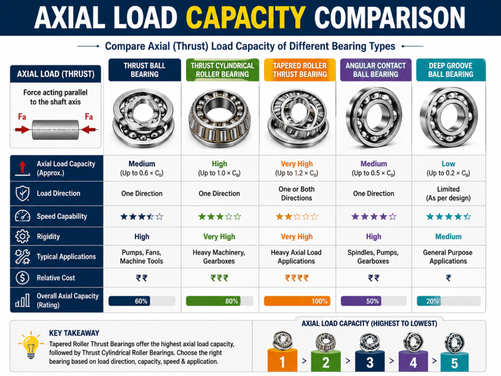
Important: Do not read this chart as an axial-load-capacity chart. Bearing manufacturers provide separate axial-load guidance and application limits. NTN, for example, publishes allowable axial-load information for deep-groove and angular-contact bearings.
Correct axial-load analysis provides several advantages.
Correctly sizing the bearing reduces overload and premature fatigue.
A properly designed thrust-support system reduces unexpected shutdowns.
Correct load selection can reduce bearing replacement frequency.
Excessive axial force can cause shaft displacement and mechanical damage. Proper analysis reduces these risks.
Excessive loading can increase friction and power consumption.
Axial-load calculations help engineers select between thrust bearings, angular-contact bearings and other bearing designs.
Axial loading itself is not necessarily harmful, but excessive or poorly controlled axial loading creates problems.
Excessive thrust can damage rolling elements and raceways.
Higher load can increase friction and heat generation.
Large axial forces can move the shaft from its intended position.
Axial movement can affect gears, couplings and seals.
High loading and temperature can accelerate lubricant degradation.
Combined axial and radial loading requires manufacturer-specific factors.
Axial loads occur in many engineering applications.
Motor shafts may experience axial forces because of magnetic forces, coupling arrangements or connected machinery.
Pump impellers can generate significant axial thrust.
Helical and bevel gears can generate axial forces.
The primary load is often axial.
Machine-tool ball screws commonly carry axial forces.
Rotating components can generate thrust that must be controlled.
Air or fluid movement can create thrust forces.
Certain conveyor arrangements can produce axial shaft forces.
Feed mechanisms frequently experience axial forces.
Gear systems are another important source of axial load.
For example, helical gears generate an axial component because the teeth are angled relative to the shaft.
For a simplified gear-force analysis:
Ft = 2T/d
where:
Depending on the gear geometry, the axial component can be related to the helix angle.
A simplified relationship is:
Fa = Ft tan β
where:
Suppose:
T = 500 Nm
d = 0.2 m
Then:
Ft = 2 × 500 / 0.2
Ft = 5,000 N
If:
β = 20°
Then:
Fa = 5,000 × tan 20°
Fa ≈ 1,820 N
Therefore, the gear can generate approximately 1.82 kN axial force.
This is why helical-gear systems frequently require bearings capable of supporting axial loads.
Possible causes:
Measure the actual operating load, calculate the equivalent dynamic load and compare it with manufacturer limits.
Possible causes:
Do not simply replace the bearing with another identical unit. First determine why the original bearing failed.
Possible causes:
Check the shaft’s axial locating system and verify the bearing arrangement.
This is one of the most common real-world conditions.
Use:
P = XFr + YFa
The correct X and Y factors depend on the bearing type and manufacturer.
Never assume X = 1 and Y = 1 unless the applicable engineering method specifically permits it.
| Feature | Axial | Radial | Combined |
| Direction | Along axis | Across axis | Both |
| Common symbol | Fa | Fr | Fa + Fr |
| Typical bearing | Thrust | Radial | Angular/contact or suitable radial bearing |
| Main concern | Thrust capacity | Radial capacity | Equivalent dynamic load |
| Calculation complexity | Low to medium | Low to medium | Medium to high |
| Common applications | Pumps, screws | Motors, rollers | Gearboxes, pumps |
Before selecting a bearing, determine:
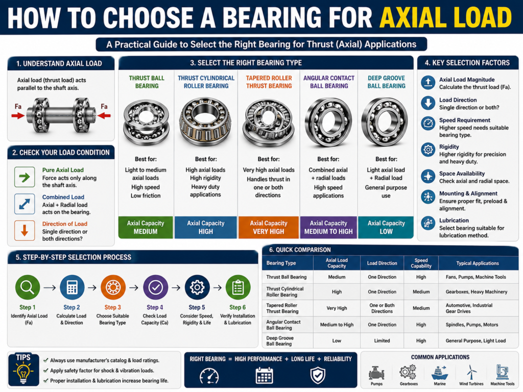
High axial load: Consider a thrust bearing.
Combined radial + axial load: Consider an angular-contact or tapered roller bearing depending on application.
Moderate axial load with radial load: A suitable deep-groove ball bearing may be appropriate, subject to manufacturer limits.
Heavy axial and radial loads: Consider tapered or spherical roller-bearing arrangements according to the application.
Axial capacity is not determined by bearing size alone.
Important factors include:
NTN’s technical material provides allowable axial-load information for different bearing families, illustrating why axial capability must be evaluated for the specific bearing design.
Before approving an axial-load design, check:
Fa = F
Fa = F cos θ
Fr = F sin θ
P = XFr + YFa
P = Fa
L10 = (C/P)³
L10 = (C/P)^(10/3)
Ft = 2T/d
Fa = Ft tan β
Always use the appropriate manufacturer’s calculation method for the selected bearing.
Axial load is a fundamental mechanical-engineering concept that directly affects bearing selection, shaft design, gearbox reliability and machine life.
The most important principle is simple:
Axial load acts parallel to the shaft axis.
However, real machines rarely experience perfectly isolated forces. Radial and axial loads often occur simultaneously, requiring engineers to calculate an equivalent dynamic bearing load.
For a pure axial thrust-bearing application:
P = Fa
For combined loading:
P = XFr + YFa
Once the equivalent load is known, bearing life can be estimated using the appropriate bearing-life equation.
The correct engineering workflow is therefore:
Identify force → Resolve components → Calculate bearing reactions → Determine equivalent load → Check dynamic rating → Check static rating → Calculate life → Verify lubrication, speed, temperature and installation.
A powerful axial-load design is not simply about choosing the biggest bearing. It is about selecting the right bearing for the actual force, speed, environment, service life and operating conditions.
For engineering design, always use the current manufacturer’s catalog and application limits for the exact bearing model. SKF and NTN both provide detailed technical information for bearing load and life calculations.
Axial load is a force acting parallel to the longitudinal axis of a shaft, bearing or mechanical component. It is also commonly called thrust load.
For a force aligned with the shaft:
Fa = F
For an angled force:
Fa = F cos θ
Axial load acts parallel to the shaft axis, while radial load acts perpendicular to the shaft axis.
Thrust bearings are specifically designed for axial loading. Angular-contact and tapered roller bearings are also commonly used where radial and axial loads occur together.
Yes. Deep-groove ball bearings can accommodate axial loads within their application limits, but their allowable axial load depends on bearing design, speed, lubrication and other factors. Manufacturer data should be consulted.
It is a calculated load that represents the effect of actual radial and axial loading in a form that can be used for bearing-life calculations.
Fa represents the applied axial load.
Fr represents the applied radial load.
Excessive axial load can increase the equivalent dynamic load and therefore reduce calculated bearing life.
Because their teeth are inclined relative to the shaft. The tangential gear force therefore has an axial component.
Use the correct bearing type, calculate the actual load, maintain proper lubrication, control contamination, ensure correct installation and verify operating conditions against manufacturer specifications.

Welcome! I am a dedicated entrepreneur running an industrial affiliate product website, helping businesses and professionals find the best tools, equipment, and resources for their needs. With a passion for industrial products and a keen eye for quality, I curate and recommend top-performing items that enhance efficiency and reliability.
Through my platform, I aim to simplify the buying process by providing valuable insights, expert reviews, and trusted affiliate links to high-quality industrial products. Whether you’re looking for the latest machinery, tools, or safety gear, I strive to connect you with the best solutions available.
Thank you for visiting, and I look forward to helping you make informed purchasing decisions!
