Our Location
Killa-Pardi, Dist. Valsad, 396125

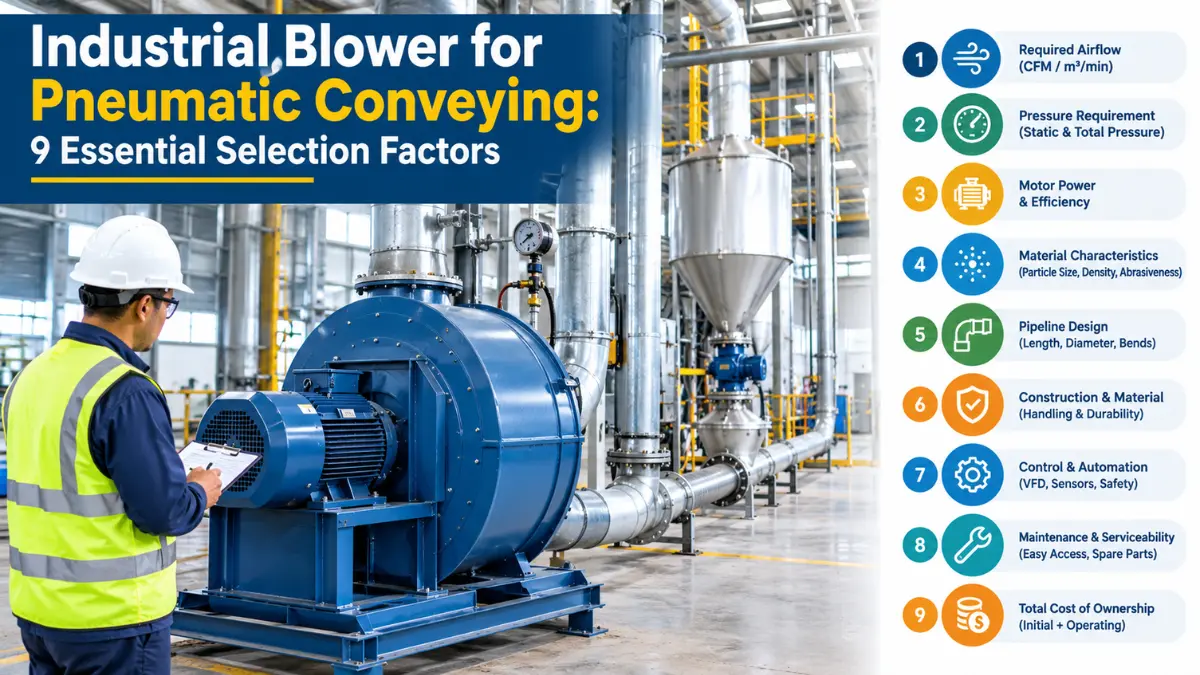
An industrial blower for pneumatic conveying is a machine that generates the airflow or air pressure required to transport dry bulk materials through pipelines. It is widely used in cement plants, food processing factories, pharmaceutical manufacturing, chemical industries, plastic processing, agriculture, and other material-handling applications.
Pneumatic conveying uses air or another suitable gas to move materials such as cement powder, flour, plastic granules, grain, fly ash, and other compatible bulk solids from one location to another.
Unlike mechanical conveying systems that use belts, screws, or bucket elevators, a pneumatic conveying system transports material through enclosed pipes. This can reduce material spillage, simplify routing, and help control dust when the system is correctly designed.
For industrial buyers in India and the USA, selecting the right pneumatic conveying blower is important for reliable material transportation, production efficiency, energy consumption, and equipment life.
A blower that supplies insufficient airflow may cause material accumulation and pipeline blockage. A blower operating at excessive pressure or airflow can waste electricity, increase operating costs, and damage sensitive materials.
Quick answer: The best industrial blower for pneumatic conveying depends on the material being transported, required material throughput, pipe diameter, conveying distance, operating pressure, air velocity, and system pressure drop. Roots blowers are commonly considered for positive-pressure conveying, while centrifugal blowers may suit certain high-airflow, lower-pressure applications. The final selection must be based on the complete system requirements and the manufacturer’s performance data.
A pneumatic conveying system uses airflow to move bulk materials through a closed pipeline. The blower supplies the required air movement, while feeders, pipes, separators, and filters control the transportation process.
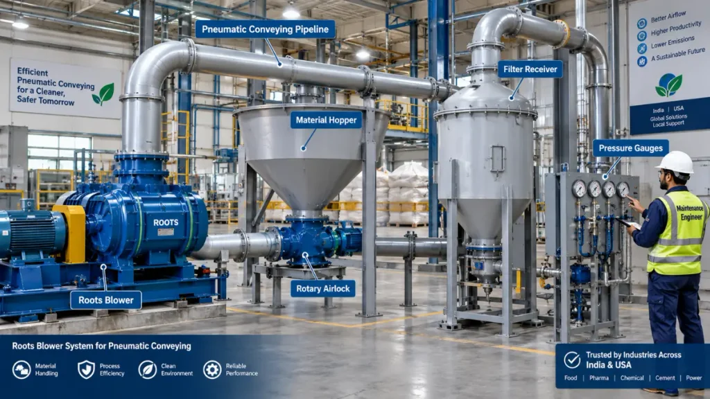
1. Industrial Blower
The pneumatic conveying blower supplies the required airflow and pressure. Depending on the system, it may be a Roots blower, centrifugal blower, or another suitable blower design.
2. Material Feeding System
A hopper, rotary airlock, screw feeder, or other feeding device introduces the material into the conveying pipeline. The feeder must be compatible with the conveying pressure and material characteristics.
3. Conveying Pipeline
The pipeline carries air and material from the feeding point to the destination. Pipe diameter, length, bends, fittings, surface conditions, and vertical lift influence system resistance.
4. Material Receiver or Separator
A cyclone separator, filter receiver, or another suitable separation device separates the conveyed solids from the transport air.
5. Air Filtration System
Filters collect fine particles and help prevent dust from entering the surrounding environment or damaging downstream equipment.
6. Control and Monitoring System
Pressure sensors, differential pressure gauges, temperature sensors, flow measurement instruments, and motor monitoring devices help operators identify abnormal operating conditions.
The blower generates airflow or pressure differences that move air through the pipeline. Material enters the system through a suitable feeding device and is carried by the moving air. At the receiving end, the material is separated from the air. The air is then filtered, discharged, or recirculated according to the system design.
In a positive-pressure system, the blower pushes air and material toward the destination. In a vacuum conveying system, a vacuum producer creates negative pressure to draw material toward the receiver.
The choice between positive pressure and vacuum conveying depends on material properties, conveying distance, pickup requirements, receiver arrangement, and the overall plant layout.
There are two major conveying approaches: dilute-phase conveying and dense-phase conveying. The appropriate method depends on the material, production rate, pipe layout, and acceptable material degradation.
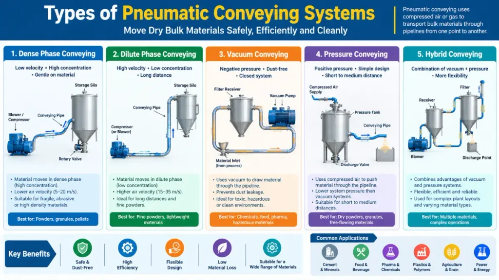
Dilute-phase conveying transports particles suspended in a relatively high-velocity air stream. The material occupies a comparatively small proportion of the conveying air volume.
This system is commonly used for materials such as grain, flour, plastic granules, and various dry powders, subject to their handling characteristics.
Advantages
Limitations
A dilute-phase pneumatic conveying blower must provide enough airflow to maintain the required material transport velocity throughout the system.
Dense-phase conveying moves material at a comparatively higher solids concentration, often using lower conveying velocities than dilute-phase systems. The exact operating principle varies with the material and system design. Some systems transport material in plugs or slugs, while others use different dense-phase flow regimes.
Dense-phase conveying can be useful for materials that are fragile, abrasive, or require reduced particle impact. However, it is not suitable for every material, and its design can be more complex.
Advantages
Limitations
| Parameter | Dilute Phase | Dense Phase |
|---|---|---|
| Material concentration | Relatively low | Relatively high |
| Air velocity | Generally higher | Often lower |
| Material degradation | Can be higher for fragile products | May be lower in suitable systems |
| Pressure requirement | Depends on system resistance | Can be relatively high |
| Design complexity | Varies by application | Often requires specialized design |
| Typical materials | Grain, many powders, plastic granules | Selected fragile, abrasive, or difficult materials |
| Blower selection | Airflow and pressure requirements | Pressure, solids loading, and conveying method |
Important: There is no universal air velocity or pressure that separates dilute-phase and dense-phase conveying. These values depend on material properties and the selected conveying technology.
Choosing the right blower type is one of the most important decisions in pneumatic conveying system design. The main options include Roots blowers, centrifugal blowers, regenerative blowers, and certain screw or other positive-displacement machines.
A Roots blower is a positive-displacement machine that uses rotating lobes to move air. It is widely considered for industrial applications requiring a relatively stable airflow over a range of operating pressures.
Roots blowers are commonly used in pneumatic conveying, wastewater aeration, industrial process air, and other applications that match their performance characteristics.
Key benefits
Limitations
A Roots blower should never be operated above its manufacturer’s permitted differential pressure, speed, temperature, or power limits.
A centrifugal blower uses a rotating impeller to transfer energy to air. It is often considered when the application requires substantial airflow and the operating pressure falls within the blower’s performance range.
Key benefits
Limitations
A regenerative blower, also called a side-channel blower or ring blower, recirculates air within its impeller and side channel to develop pressure or vacuum.
It may be suitable for relatively low-flow process applications, light-duty conveying, or specialized pneumatic handling where the required airflow and pressure are within its performance limits. It should not automatically be selected for heavy-duty bulk material conveying.
| Blower type | Typical selection consideration | Main limitation |
|---|---|---|
| Roots blower | Positive-displacement conveying duties | Pressure, temperature, noise, and power limits |
| Centrifugal blower | Higher airflow within a suitable pressure range | Performance varies with system resistance |
| Regenerative blower | Smaller-flow, specialized applications | Limited suitability for demanding bulk conveying |
| Screw blower | Selected continuous industrial air applications | Higher initial cost in some installations; model-dependent performance |
Which blower is best?
For many positive-pressure industrial conveying systems, a Roots blower is a practical candidate. A centrifugal blower can be appropriate when the required airflow and pressure match its performance curve. The final decision should compare total lifecycle cost, efficiency, operating conditions, material properties, and maintenance requirements.
An industrial blower for pneumatic conveying should never be selected using motor horsepower or airflow alone. The following nine factors help establish the correct requirements.
The material being transported directly affects the conveying system. Important characteristics include:
For example, plastic granules may require different handling conditions from cement powder. Fragile food ingredients may require a different conveying strategy from abrasive mineral powders.
Moisture-sensitive materials may need dry conveying air. Combustible dust may require an appropriately designed dust-control and explosion-protection system.
Material flow rate indicates how much solid material must be transported per unit of time. It is commonly expressed in:
Suppose a factory must transport 5 tonnes of material per hour.
Convert tonnes to kilograms: 5 tonnes/h × 1,000 = 5,000 kg/h.
The conveying system must therefore handle 5,000 kg/h under the specified operating conditions.
This does not mean the blower itself has a capacity of 5,000 kg/h. The blower transports the conveying air, while the feeder and pipeline system transport the solid material. The required airflow depends on the material throughput, conveying phase, solids loading, line geometry, and operating velocity.
Airflow is one of the most important specifications for an industrial pneumatic conveying blower. Common units include:
Do not assume that CFM, ACFM, and SCFM are interchangeable. Actual and standardized airflow values may differ because of temperature, pressure, humidity, and the selected reference conditions. The airflow requirement must be determined from the conveying system design rather than selected from a generic blower chart.
The blower must overcome the total pressure losses in the conveying system. These losses may include:
Pressure may be expressed in Pa, kPa, mbar, or psi. Useful conversions include:
For positive-pressure conveying, the required blower differential pressure must be established using a suitable engineering calculation or a validated system design.
Pipe diameter affects airflow velocity and system resistance. A smaller pipe generally produces a higher air velocity at a given flow rate, but it can also increase friction losses.
A larger pipe generally reduces velocity at a given flow rate, but excessive reduction in velocity may allow material to settle and cause blockages. The design must consider:
A pipeline containing many bends may have significantly different pressure requirements from a straight pipeline of the same length.
Air velocity is the speed of air moving through the pipeline.
The basic formula is: Air velocity = Volumetric airflow ÷ Pipe cross-sectional area
V = Q/A
Where:
The minimum conveying velocity depends on the material, particle size, density, solids loading, and conveying method. If air velocity is too low, particles may settle or the pipeline may block. If it is too high, energy consumption, particle degradation, and pipeline erosion may increase.
For this reason, a pneumatic conveying system must be designed around a material-specific operating velocity rather than a universal number.
The blower motor must provide enough power to operate at the required airflow and pressure. Power depends on the actual duty point and the efficiency of the blower, motor, and drive system. Important considerations include:
Motor nameplate power alone does not determine the actual electricity consumption.
The operating environment can influence blower performance and service life. Consider:
For plants in India, high ambient temperatures and dusty industrial environments may require particular attention to ventilation, cooling, filtration, and motor protection.
For US installations, buyers must also evaluate applicable electrical codes, workplace safety requirements, and any industry-specific standards.
The purchase price is only one part of the total cost of an industrial blower. A lifecycle assessment should consider:
For continuous-duty factories, energy consumption and unplanned downtime can have a greater long-term financial impact than the initial price difference between blower models.
A preliminary airflow calculation can help engineers understand the relationship between pipe diameter and air velocity. However, this calculation alone cannot determine the complete conveying-system capacity or final blower size.
Assume the following illustrative design values:
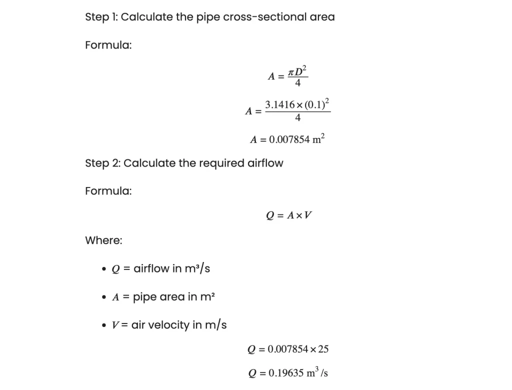
| Parameter | Illustrative result |
|---|---|
| Pipe internal diameter | 100 mm |
| Pipe area | 0.007854 m² |
| Assumed air velocity | 25 m/s |
| Calculated airflow | 0.19635 m³/s |
| Airflow | Approximately 707 m³/h |
| Airflow | Approximately 416 CFM |
Engineering caution: The assumed 25 m/s velocity is for demonstrating the calculation, not a universal design recommendation. The correct velocity must be established for the actual material and conveying regime. Confirm whether the specified airflow is actual or standardized volume.
The final blower duty point also requires the system pressure calculation, material throughput, solids loading, feeding method, and manufacturer’s performance data.
The required blower pressure depends on the total resistance of the pneumatic conveying system. A simplified pressure budget can be expressed as:

Where:
Assume the following illustrative pressure losses for a pneumatic conveying system:
| Component | Pressure loss |
|---|---|
| Straight conveying pipes | 2.0 kPa |
| Elbows and bends | 1.0 kPa |
| Filter and separator | 1.5 kPa |
| Material conveying | 3.0 kPa |
| Total pressure loss | 7.5 kPa |
Therefore,

The calculated system pressure requirement is 7.5 kPa (75 mbar). The final blower selection must also account for the manufacturer’s performance curve, operating airflow, material properties, leakage, and an appropriate engineering margin.
Important: This is an illustrative calculation, not a final equipment specification. Pneumatic conveying pressure requirements can vary significantly between dilute-phase and dense-phase systems. Select a blower using the required airflow and pressure together at the same operating point.
Suppose a preliminary engineering assessment identifies these illustrative pressure losses:
| Component | Assumed pressure loss |
|---|---|
| Straight pipe | 4 kPa |
| Bends and fittings | 2 kPa |
| Material conveying | 5 kPa |
| Filter and receiver | 3 kPa |
| Other components | 1 kPa |
| Total illustrative pressure loss | 15 kPa |
The arithmetic total is: 4 + 2 + 5 + 3 + 1 = 15 kPa.
These figures are hypothetical and must not be used as standard pressure allowances. Actual losses should be calculated or measured for the real system. A blower operating point must be selected to meet the required airflow at the necessary differential pressure, with appropriate consideration of operating variation and the manufacturer’s limits.
For vacuum conveying, the design must account for the vacuum level and pressure differences across the system rather than treating the application as an ordinary positive-pressure installation.
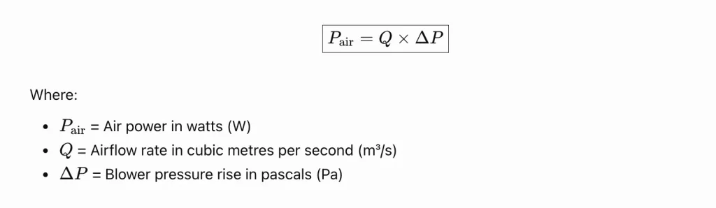
A simplified engineering estimate of the power transferred to the air is:
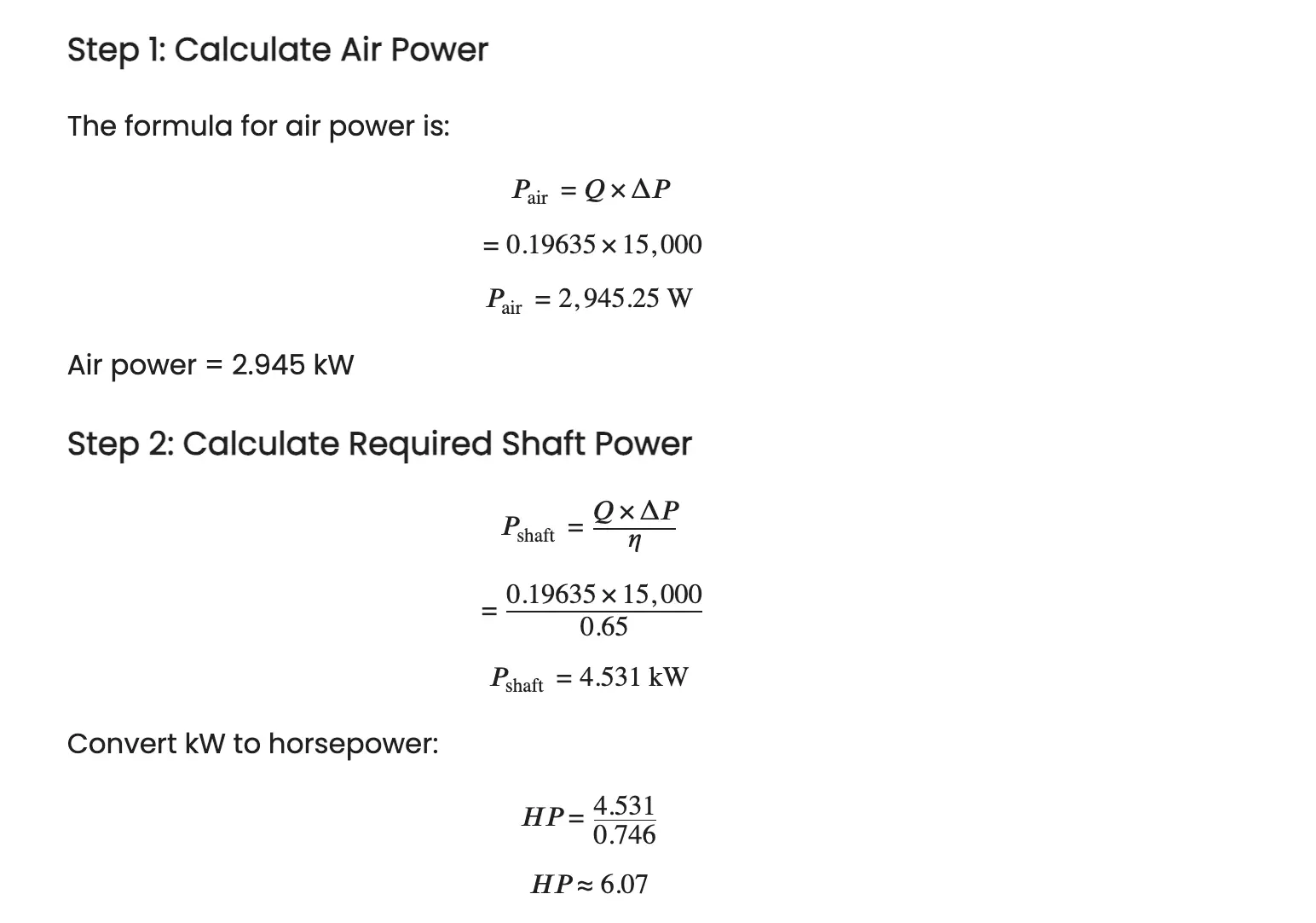
Use the illustrative airflow from the previous calculation:
| Parameter | Calculated value |
|---|---|
| Airflow | 0.19635 m³/s |
| Airflow in CFM | Approximately 416 CFM |
| Differential pressure | 15 kPa |
| Air power | 2.945 kW |
| Required shaft power | 4.531 kW |
| Required shaft horsepower | 6.07 HP |
| Preliminary motor selection | 7.5 HP (5.5 kW) |
Recommendation: A 7.5 HP motor may be a reasonable preliminary selection, provided the blower manufacturer’s performance curve confirms the required airflow at 15 kPa and the motor has sufficient power margin.
Important engineering note: A differential pressure of 15,000 Pa (15 kPa) is relatively high for many conventional industrial blowers. Confirm whether a centrifugal blower, high-pressure blower, or Roots-type positive-displacement blower is suitable. Also verify whether the stated 65% efficiency represents blower shaft-to-air efficiency; motor efficiency and drive losses may increase the required electrical input.
This is not a final motor selection. The assumed pressure, efficiency, and airflow must be validated. The motor rating must then be selected using the manufacturer’s shaft-power requirements, motor efficiency, starting conditions, service conditions, and applicable design margins.
A standard motor rating should not be chosen solely by rounding this estimate. A qualified engineer should verify the blower operating point and the manufacturer’s recommended motor size.
Pneumatic conveying is used across multiple industries, but each application has specific material-handling requirements.
Cement plants use pneumatic conveying for moving cement powder, fly ash, and other compatible dry materials. Important selection considerations include:
A Roots blower may be suitable for some positive-pressure cement conveying duties, depending on the required flow and pressure.
Food factories use pneumatic conveying to move flour, sugar, starch, grain, and selected food ingredients. Important considerations include:
The blower and conveying system must be compatible with the required sanitation and product-quality standards.
Plastic processing plants transport pellets, granules, and selected powders between storage silos, dryers, hoppers, and processing machines. The system should account for:
The correct conveying velocity helps avoid excessive particle damage and unstable material flow.
Pharmaceutical production may require the transfer of powders and granules under controlled conditions. Selection should consider:
The blower type and system configuration must comply with the applicable process and quality requirements.
Power plants may use pneumatic conveying for fly ash and other bulk materials. The design should consider abrasive particles, operating temperature, solids loading, conveying distance, and filtration requirements.
A blower suitable for one fly-ash system may not be appropriate for another because material characteristics and pipeline conditions can differ.
Agricultural facilities use pneumatic systems for grain, seeds, and other suitable bulk materials.
Selection factors include product damage, dust generation, material moisture, throughput, and seasonal operating conditions. Where combustible dust is present, the system requires a suitable dust-hazard assessment and appropriate protection measures.
Correct blower selection is only one part of reliable pneumatic conveying. System design, installation, operating conditions, and maintenance also influence performance.
Possible causes:
Recommended checks: Inspect the inlet filter, airflow measurement, speed, leakage, and system pressure. Compare actual operating conditions with the blower manufacturer’s performance data.
Possible causes:
Recommended checks: Follow the system’s safe shutdown and blockage-clearing procedure. Inspect feeding, material condition, pressure trends, and operating velocity before restarting.
Never open a pressurized conveying line or attempt to clear a blockage while the equipment is operating.
Possible causes:
Recommended checks: Measure electrical power, airflow, and differential pressure at the same operating condition. Investigate system resistance and compare the actual duty point with the design requirement.
Possible causes:
Recommended checks: Verify pressure, temperature, cooling, airflow, and maintenance condition against the manufacturer’s operating limits.
Possible causes:
Recommended checks: Use a planned vibration inspection, check alignment and foundation conditions, and investigate abnormal operating noise.
Do not continue operating equipment that shows signs of serious mechanical failure.
Preventive maintenance helps reduce unplanned shutdowns and supports reliable pneumatic conveying.
Follow the manufacturer’s recommended maintenance schedule for bearings, seals, lubrication, alignment, internal clearances, electrical protection, and other serviceable components.
The inspection frequency should be adjusted according to operating hours, material abrasiveness, dust loading, environmental conditions, and manufacturer instructions.
Electricity is a major operating expense for many continuously operating industrial conveying systems. The most effective energy-saving measures begin with measuring actual operating conditions.
An oversized blower can consume unnecessary power if it operates away from its intended duty point. An undersized blower may fail to meet the material transport requirement.
Select the blower using the required airflow and pressure rather than horsepower alone.
Review pipeline routing, bends, fittings, filter resistance, and other sources of pressure drop.
Any design change must preserve the required conveying velocity and reliable solids transport.
A loaded filter can increase pressure drop and energy consumption.
Use differential pressure monitoring and follow the filter manufacturer’s maintenance recommendations.
Leaks can waste energy and reduce the airflow available for material transportation.
Inspect joints, seals, valves, and connections using an approved maintenance procedure.
A variable-frequency drive (VFD) can control motor speed where the blower and process are suitable for variable-speed operation.
However, energy savings depend on the blower type, system resistance, conveying stability, and the required operating range. Do not assume that reducing speed will always produce the same savings.
Track electricity use against production throughput. Useful performance indicators include:
For example, a blower consuming 10 kW for 4,000 hours per year uses: 10 × 4,000 = 40,000 kWh annually.
At an illustrative electricity rate of ₹8 per kWh, the annual energy cost would be:
40,000 × ₹8 = ₹320,000.
At an illustrative US electricity rate of $0.12 per kWh, the same consumption would cost:
40,000 × $0.12 = $4,800.
These are example rates, not current electricity tariffs. Actual costs depend on the plant’s tariff, demand charges, taxes, and operating schedule.
Safety must be considered during blower selection, installation, commissioning, operation, and maintenance. Important precautions include:
Dust explosion hazards: Combustible dusts may require a formal hazard assessment and suitable explosion prevention, venting, suppression, isolation, and dust collection measures.
For US facilities, evaluate applicable OSHA requirements, NFPA standards where relevant, and local electrical and fire codes. For Indian facilities, review applicable BIS standards, electrical safety rules, factory requirements, and local statutory obligations.
The exact requirements depend on the process, facility, material, and jurisdiction.
Before requesting a quotation from a blower manufacturer or industrial equipment supplier, prepare the following information.
| Required information | Example or unit |
|---|---|
| Material type | Cement, flour, plastic pellets |
| Material flow rate | kg/h or tonnes/h |
| Conveying method | Dilute phase or dense phase |
| Pipeline internal diameter | mm or inches |
| Horizontal distance | m or ft |
| Vertical lift | m or ft |
| Number and type of bends | Quantity and geometry |
| Required airflow | CFM or m³/h |
| Required pressure or vacuum | kPa, mbar, or psi |
| Operating temperature | °C or °F |
| Operating hours | Hours/day and days/year |
| Electrical supply | Voltage, frequency, and phase |
| Dust and safety requirements | Material-specific assessment |
| Filtration and receiver details | Type and pressure drop |
| Installation environment | Indoor, outdoor, dusty, hazardous |
Ask the supplier to confirm the guaranteed airflow and pressure at the specified operating condition, the required motor rating, the operating limits, and the expected performance under the actual system conditions.
Also request the blower performance curve or operating data, noise information, maintenance requirements, and recommended protective accessories.
A professional pneumatic conveying design should verify the entire system, not just the blower.
An industrial blower for pneumatic conveying is an essential component of many modern bulk material handling systems. Correct blower selection supports reliable production, controlled material transport, energy efficiency, and lower maintenance costs.
Before purchasing a pneumatic conveying blower, evaluate the material properties, required throughput, pipeline diameter, conveying distance, pressure drop, airflow, motor power, and operating environment.
Roots blowers, centrifugal blowers, regenerative blowers, and other industrial air-moving machines each have specific operating ranges. The best blower is the one that meets the complete system requirements safely and efficiently.
For industrial buyers in India and the USA, the most reliable approach is to combine preliminary airflow and pressure calculations with professional system design and verified manufacturer performance data.
Explore more industrial engineering guides on RetailGlobe.in to understand industrial blower selection, blower energy consumption, preventive maintenance, troubleshooting, and other practical equipment topics.
Technical values in the worked examples are illustrative calculations, not universal design specifications. Before publication, verify any product-specific claims and add authoritative references relevant to pneumatic conveying, blower performance testing, workplace safety, and applicable local standards. Avoid repeating keywords unnaturally; use them where they genuinely help readers understand the subject.
References For More Study:
An industrial blower for pneumatic conveying supplies the airflow or pressure difference required to transport bulk materials through an enclosed pipeline. It is used in cement, food processing, plastics, chemicals, agriculture, and other industries.
A Roots blower is commonly considered for positive-pressure conveying systems. A centrifugal blower may be suitable for applications requiring higher airflow at a compatible pressure. The best option depends on material properties, required airflow, system pressure drop, and conveying method.
A pneumatic conveying blower is an industrial air-moving machine used to support the transportation of powders, granules, pellets, and other bulk solids through pipes using air or another suitable gas.
Calculate the pipeline cross-sectional area and multiply it by the required air velocity:
Q = A × v.
For a circular pipe, A = πD²/4. Convert the resulting volumetric flow from m³/s to CFM as needed. The design velocity must be appropriate for the material and conveying regime.
A Roots blower is a positive-displacement machine that moves a relatively defined volume of air per revolution, subject to leakage and operating conditions. A centrifugal blower uses an impeller to transfer energy to air, and its airflow depends on the system operating point. Their suitability depends on the required pressure, airflow, efficiency, and process conditions.
There is no single pressure requirement for every pneumatic conveying system. Pressure depends on pipeline length and diameter, bends, material throughput, air velocity, filters, elevation, and the conveying method.
Dilute-phase conveying transports solids suspended in a relatively high-velocity airflow. It is used for many dry powders, grains, and granules, subject to their material characteristics and the system design.
Dense-phase conveying moves solids at a comparatively higher material concentration and often lower air velocity. It can suit selected fragile or abrasive materials, but requires an appropriate pressure and feeding design.
A centrifugal blower may be suitable for certain cement powder conveying systems if its airflow and pressure performance meet the design requirements. The engineer must verify the pressure drop, material loading, dust control, and manufacturer’s operating limits.
Electricity consumption depends on actual input power and operating hours.
Annual consumption in kWh = Average input power in kW × Annual operating hours.
For example, a 15 kW electrical input operating for 4,000 hours uses 60,000 kWh annually.
Common causes include insufficient conveying velocity, excessive material feed, moisture, cohesive material, poor pipeline geometry, and incorrect pressure or airflow. Diagnose the underlying cause before restarting the system.
A VFD can help control motor speed and airflow when the blower and conveying process support variable-speed operation. The design must maintain stable material transport and respect blower operating limits.
Inspect the blower regularly and follow the manufacturer’s maintenance schedule. Daily checks may include pressure, temperature, noise, and vibration, while filters, bearings, drives, and other components require inspection at intervals appropriate to the equipment and operating environment.
CFM means cubic feet per minute, while m³/h means cubic metres per hour.
1 m³/h ≈ 0.5886 CFM.
Always check whether airflow is stated as actual or standardized volume.
Start with the material throughput, conveying method, pipeline dimensions, required air velocity, pressure drop, operating temperature, and annual operating hours. Then compare suitable blower performance curves, motor power, efficiency, safety requirements, service support, and lifecycle cost.

Welcome!
I am the Founder of RetailGlobe.in and a digital content creator focused on industrial tools, machinery, equipment, and technical product information. I develops product guides, reviews, comparisons, and practical buying insights to help engineers, technicians, workshop owners, and industrial buyers make informed purchasing decisions in India and the USA.
Thank you for visiting, and I look forward to helping you make informed purchasing decisions!
