Our Location
Killa-Pardi, Dist. Valsad, 396125

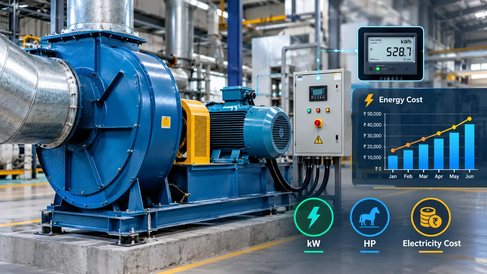
Industrial blowers can run for thousands of hours every year, making electricity consumption an important part of their total operating cost. A blower may look like a relatively simple machine, but its actual energy consumption depends on several factors, including airflow, static pressure, total pressure, blower efficiency, motor efficiency, operating hours, speed and system resistance.
Choosing a blower only by motor HP or maximum CFM can therefore result in unnecessary electricity consumption.
The better approach is to calculate the power required at the actual operating point.
This guide explains industrial blower energy consumption, how to calculate kW and HP, how to estimate electricity cost, how blower efficiency affects energy use, and how a VFD can reduce power consumption in variable-flow applications.
It also includes practical formulas, conversion tables, a factory example and a simple method for estimating annual blower operating cost.
Industrial blower energy consumption is the amount of electrical energy required to operate a blower for a specific period. Electrical energy is normally measured in:
The instantaneous electrical demand is measured in:
For example, if a blower motor draws 15 kW continuously for 1 hour: Energy consumed = 15 kWh
If the same blower operates for 10 hours: Energy consumed = 15 × 10 = 150 kWh
The basic electricity-cost formula is: Electricity Cost = Energy Consumption × Electricity Rate
Therefore: Cost = kW × Operating Hours × Electricity Rate
This simple equation becomes extremely useful when comparing industrial blowers.
A blower running only a few hours per week may have a low electricity cost.
The blower may cost about ₹5.76 lakh per year in electricity. So even a small improvement in blower efficiency can become financially important when equipment operates continuously.
The U.S. Department of Energy notes that fan systems can provide significant energy-saving opportunities and recommends looking at the complete system rather than only the individual fan or motor.
Ref.: https://www.energy.gov/cmei/ito/fan-systems?utm_source=chatgpt.com
The electrical power required by an industrial blower depends mainly on:
| Factor | Effect on Energy Consumption |
|---|---|
| Airflow | Higher airflow generally requires more power |
| Static/total pressure | Higher pressure requires more power |
| Blower efficiency | Higher efficiency reduces required power |
| Motor efficiency | Higher motor efficiency reduces electrical losses |
| Operating hours | More hours mean higher annual kWh |
| Fan speed | Speed changes can have a major effect on power |
For centrifugal fan and blower systems, speed is particularly important because the affinity laws indicate that, under appropriate conditions, flow varies approximately with speed, pressure with speed², and power with speed³.
The fundamental relationship is: Power = Airflow × Pressure ÷ Efficiency
For SI units: P(kW) = [Q(m³/s) × ΔP(Pa)] ÷ [1000 × η]
Where:
For example:
70% efficiency = 0.70
80% efficiency = 0.80
The ideal air power before losses can be represented as: P_air = Q × ΔP
The actual blower input power is higher because the blower is not 100% efficient. Engineering references similarly express fan power as pressure × volume flow divided by efficiency.
Ref. : https://www.engineeringtoolbox.com/amp/fans-efficiency-power-consumption-d_197.html
Many industrial blower specifications use CFM and inches of water gauge instead of m³/s and Pascal. A commonly used approximate formula is: BHP = (CFM × Pressure) ÷ (6356 × η)
Where:
This is useful for preliminary calculations. Final motor selection should always be checked against the manufacturer’s blower performance curve and power data. Engineering references provide the same CFM/in. WG relationship for estimating air and brake horsepower.
Ref. : https://www.engineeringtoolbox.com/ahp-bhp-air-brake-horsepower-d_1582.html#gsc.tab=0
The basic conversion is: 1 HP = 0.746 kW
Therefore: kW = HP × 0.746 and: HP = kW ÷ 0.746
| Motor HP | Approx. Motor Rating |
|---|---|
| 1 HP | 0.746 kW |
| 2 HP | 1.49 kW |
| 3 HP | 2.24 kW |
| 5 HP | 3.73 kW |
| 7.5 HP | 5.60 kW |
| 10 HP | 7.46 kW |
| 15 HP | 11.19 kW |
| 20 HP | 14.92 kW |
| 25 HP | 18.65 kW |
| 30 HP | 22.38 kW |
| 40 HP | 29.84 kW |
| 50 HP | 37.30 kW |
These are nominal mechanical-power conversions. Actual electrical input can be higher because motor, drive and transmission losses must be considered.
Suppose an industrial blower operates at:
So the estimated blower mechanical/input requirement at this stage is approximately: 10.1 kW
The actual electrical input will depend on the motor efficiency, drive losses and transmission arrangement.
This is where many basic blower calculations become incomplete.
If a VFD is used, the drive also introduces some losses. Therefore, a simplified system calculation can be represented as:
Electrical Input kW ≈ Air Power ÷ (Blower Efficiency × Motor Efficiency × Drive Efficiency × Transmission Efficiency)
For a direct-coupled blower, transmission efficiency may be close to 100%, while belt-driven systems introduce additional losses.
A useful practical equation is:
P_electrical = Q × ΔP ÷ (η_blower × η_motor × η_drive × η_transmission)
Where:
Then convert watts to kilowatts: kW = P(W) ÷ 1000
This approach gives a much better estimate than simply looking at the motor nameplate HP.
Once electrical input power is known, annual energy consumption is easy to calculate.
Formula:
Annual Energy Consumption (kWh) = Input Power (kW) × Operating Hours/Year
Then: Annual Electricity Cost = Annual kWh × Electricity Rate
Example:
Suppose:
Annual operating hours: 16 × 300 = 4,800 hours
Annual energy: 15 × 4,800 = 72,000 kWh
Annual electricity cost: 72,000 × ₹8 = ₹576,000
So the estimated annual electricity cost is: ₹5.76 lakh/year
Assuming an electricity rate of ₹8/kWh:
| Blower Input | 2,000 h/year | 4,000 h/year | 6,000 h/year | 8,000 h/year |
|---|---|---|---|---|
| 5 kW | ₹80,000 | ₹1.60 lakh | ₹2.40 lakh | ₹3.20 lakh |
| 10 kW | ₹1.60 lakh | ₹3.20 lakh | ₹4.80 lakh | ₹6.40 lakh |
| 15 kW | ₹2.40 lakh | ₹4.80 lakh | ₹7.20 lakh | ₹9.60 lakh |
| 20 kW | ₹3.20 lakh | ₹6.40 lakh | ₹9.60 lakh | ₹12.80 lakh |
| 30 kW | ₹4.80 lakh | ₹9.60 lakh | ₹14.40 lakh | ₹19.20 lakh |
| 50 kW | ₹8.00 lakh | ₹16.00 lakh | ₹24.00 lakh | ₹32.00 lakh |
Important: Actual industrial electricity bills may include demand charges, time-of-use rates, taxes and other utility components. DOE’s industrial fan guidance distinguishes energy charges from demand charges, so a simple kWh calculation should be treated as an operating-energy estimate rather than a complete utility bill model.
Let’s consider a practical industrial ventilation example.
Factory dimensions:
Suppose the duct system has the following estimated pressure losses:
| Component | Pressure Loss |
|---|---|
| Main duct | 250 Pa |
| Elbows/bends | 180 Pa |
| Filters | 300 Pa |
| Outlet grille | 120 Pa |
| Allowance | 150 Pa |
| Total | 1,000 Pa |
Therefore, the required operating point becomes approximately: 15,525 CFM @ 1,000 Pa
This is far more useful than saying:
“I need a 20 HP blower.”
The blower should first be selected based on the required airflow + pressure operating point, then the motor power should be checked.
A suitable commercial motor would then need to be selected by checking the manufacturer’s actual fan curve, motor loading, starting requirements and available standard motor ratings. This example is for demonstrating the calculation method; it is not a final equipment specification.
The actual cost will change with measured operating power, electricity tariff, operating schedule, motor loading and system conditions.
A 15 HP motor does not necessarily consume exactly: 15 × 0.746 = 11.19 kW
That number represents nominal mechanical horsepower conversion, not necessarily the electrical input from the grid. Actual consumption depends on:
For a three-phase motor, an approximate electrical input calculation can be made using:
kW = √3 × V × I × PF ÷ 1000
Where:
For example, if a motor operates at:
Then: kW ≈ 1.732 × 415 × 20 × 0.85 ÷ 1000 ≈ 12.2 kW
For an actual plant energy audit, a properly installed power meter or power analyzer is preferable.
DOE’s fan-system guidance specifically describes direct measurement using voltage, current and power factor, or using a wattmeter to determine energy costs.
Consider two blowers delivering the same airflow and pressure.
The second blower needs less input power for the same useful air power, assuming comparable operating conditions. This becomes significant when the blower runs continuously.
Example:
A blower performance curve helps determine how the machine behaves at different airflow and pressure conditions. Typical curves may show:
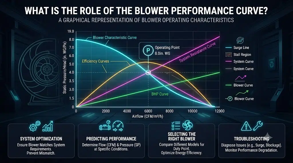
The actual operating point is determined by the interaction between the blower curve and the system resistance curve. When estimating energy consumption, do not use the blower’s maximum CFM as the actual operating airflow unless the manufacturer specifies that operating condition.
A blower advertised as: 20,000 CFM
may produce much less than 20,000 CFM once connected to ductwork, filters and process equipment.
Variable frequency drives, or VFDs, can control motor speed. For centrifugal fans and blowers operating under suitable variable-torque conditions, the affinity laws are approximately:
Q₂/Q₁ = N₂/N₁ and P₂/P₁ = (N₂/N₁)³
Where:
This means a relatively small reduction in speed can produce a much larger reduction in theoretical fan power.
DOE describes centrifugal fans and blowers as variable-torque loads and notes the cubic relationship between horsepower requirement and speed under affinity-law conditions.
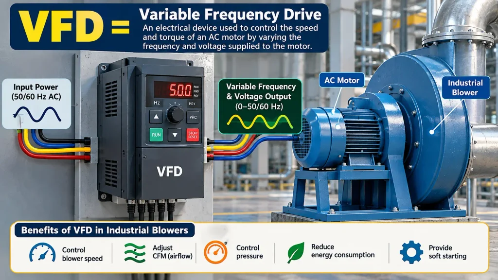
Suppose a centrifugal blower consumes: 20 kW at 100% speed
If speed is reduced to: 80%
The ideal affinity-law power ratio is: 0.8³ = 0.512
Estimated fan power: 20 × 0.512 = 10.24 kW
The theoretical saving is: 20 − 10.24 = 9.76 kW
At 5,000 hours/year: 9.76 × 5,000 = 48,800 kWh
At ₹8/kWh: 48,800 × ₹8 = ₹390,400/year
This is an illustrative affinity-law calculation, not a guarantee of actual electrical savings. Real systems can deviate because of controls, system resistance, motor/drive efficiency, minimum-speed limits and process requirements.
A VFD can be particularly relevant when airflow demand changes during production. Examples include:
If a blower must operate at full speed all the time even when the process requires less airflow, there may be an opportunity to reduce energy consumption through appropriate speed control.
DOE’s industrial guidance identifies variable-flow fan systems as attractive candidates for adjustable-speed control because relatively small speed changes can significantly affect driven-equipment horsepower. However, VFD selection should be based on the motor, blower, control strategy and process requirements.
A damper can reduce airflow by increasing system resistance. A VFD changes blower speed.
For a centrifugal blower, reducing speed can often be more energy-efficient than continuously throttling airflow with a damper, provided the process and system are suitable.
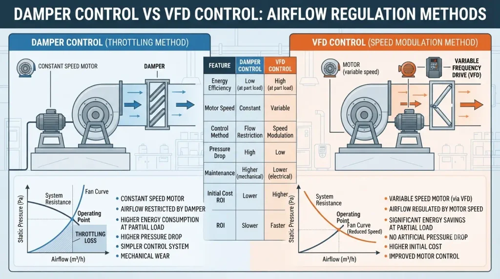
DOE’s Better Plants guidance lists variable-speed control among the important energy-performance measures for fan systems. This does not mean every blower should automatically receive a VFD. The economic benefit depends on:
An oversized blower may operate away from its intended operating point. Select the blower according to: Required CFM + Required Pressure rather than selecting the biggest available motor.
Pressure losses can come from:
Reducing system resistance can lower the pressure requirement.
A dirty filter can increase pressure drop. The blower then has to work against greater resistance. For systems with continuously increasing filter pressure drop, monitoring the differential pressure can help identify when maintenance is needed.
For belt-driven blowers:
Transmission losses directly affect electrical consumption.
Dust accumulation on an impeller can affect balance and aerodynamic performance. Inspect for:
A blower operating far from its intended design point may provide poor efficiency.
Compare actual: CFM + Pressure + kW
with the manufacturer’s performance curve.
For an operating industrial blower, record:
The DOE MEASUR platform includes fan-analysis tools for calculating fan power, flow, pressure and efficiency from measurements.
Use this checklist before replacing or upgrading a blower.
| Parameter | Measurement |
|---|---|
| Blower type | Centrifugal / axial / regenerative |
| Airflow | CFM or m³/h |
| Static pressure | Pa / mmWG / in. WG |
| Total pressure | Pa / in. WG |
| Motor rating | HP / kW |
| Actual electrical input | kW |
| Voltage | V |
| Current | A |
| Power factor | PF |
| Motor efficiency | % |
| Blower efficiency | % |
| RPM | rpm |
| Operating hours | h/year |
| Electricity tariff | ₹/kWh or $/kWh |
| Control method | Damper / VFD / other |
| Filter condition | Clean / dirty |
| Belt condition | Good / poor |
| Annual energy | kWh/year |
| Annual energy cost | Currency/year |
| Air Power | P_air = Q × ΔP |
| Blower Power | P_blower = Q × ΔP ÷ η_blower |
| Electrical Power | P_electrical = Q × ΔP ÷ (η_blower × η_motor × η_drive × η_transmission) |
| Annual Energy | Energy = kW × Operating Hours |
| Electricity Cost | Cost = kWh × Electricity Rate |
| HP to kW | kW = HP × 0.746 |
| kW to HP | HP = kW ÷ 0.746 |
| Three-Phase Electrical Input | kW = √3 × V × I × PF ÷ 1000 |
| Ventilation CFM | CFM = Room Volume × ACH ÷ 60 |
| Fan Affinity Law | Q ∝ N Pressure ∝ N² Power ∝ N³ |
These formulas are useful for preliminary engineering calculations. Final equipment selection should use the manufacturer’s certified performance data and the actual system operating point.
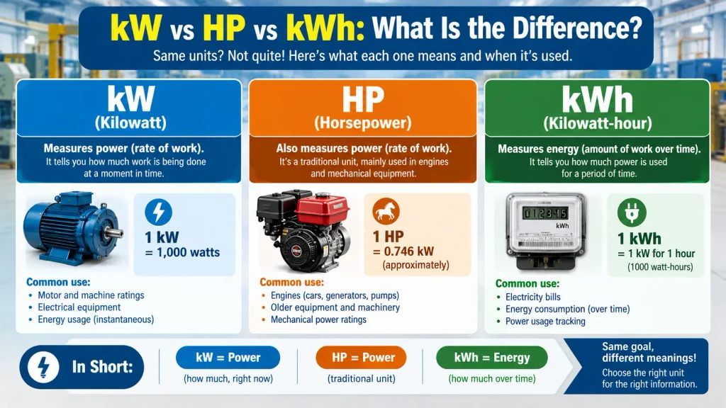
This is a common source of confusion.
| Term | Meaning |
|---|---|
| W | Unit of power |
| kW | 1,000 watts of power |
| HP | Horsepower, a power unit |
| kWh | Energy consumed over time |
| kW × hours | Energy |
| ₹/kWh | Electricity energy price |
For example:
Mistake 1: Assuming Motor HP Equals Electricity Consumption
Mistake 2: Calculating Power From CFM Alone
Mistake 3: Ignoring Efficiency
Mistake 4: Ignoring Operating Hours
Mistake 5: Selecting the Blower From Maximum CFM
Mistake 6: Ignoring System Resistance
Mistake 7: Assuming VFD Savings Are Always Cubic
Therefore, VFD energy savings should be calculated from the actual blower and system operating conditions, rather than assuming that every speed reduction will produce exactly cubic savings.
Industrial blower energy consumption should be evaluated using the complete operating system, not simply the motor nameplate.
For centrifugal blowers with variable airflow requirements, appropriate speed control can offer significant energy-saving potential because fan power can vary approximately with the cube of speed under affinity-law conditions.
The most important practical rule is:
Do not evaluate an industrial blower only by HP or maximum CFM. Evaluate the actual CFM, pressure, efficiency and electrical input at the operating point.
For a factory running thousands of hours each year, this approach can help identify oversized equipment, excessive system resistance, inefficient operating points and opportunities for speed control.
A proper blower energy assessment should ultimately compare:
CFM + Static Pressure + Total Pressure + kW + Efficiency + Operating Hours + Electricity Cost
That gives plant engineers, maintenance teams and industrial buyers a much clearer picture of the blower’s true operating cost.
Use:
P(kW) = Q(m³/s) × ΔP(Pa) ÷ [1000 × efficiency]
Then account for motor, drive and transmission efficiency to estimate electrical input.
If it operates continuously for one hour:
10 kWh
For 10 hours:
100 kWh
For 4,000 hours/year:
40,000 kWh/year
Use:
Annual Cost = Input kW × Annual Operating Hours × Electricity Rate
For example:
15 kW × 4,000 h × ₹8/kWh
= ₹480,000/year
Not necessarily by itself. Power depends on both airflow and pressure, together with efficiency.
Generally yes. For a given airflow and efficiency, increasing pressure increases the required air power.
20 HP corresponds to approximately:
20 × 0.746 = 14.92 kW
But this is a mechanical-power conversion, not necessarily the blower’s actual electrical input.
Actual electrical consumption depends on motor efficiency, loading, drive losses and operating conditions.
A VFD can be useful when the blower has variable airflow requirements. For suitable centrifugal blower systems, reducing speed can substantially reduce theoretical power demand according to the affinity laws.
Common measures include:
Avoid oversizing
Reduce unnecessary pressure losses
Clean filters
Maintain belts
Maintain the impeller
Check operating point
Use appropriate speed control
Measure actual kW and airflow
Neither should be considered alone.
The important operating specification is:
Required CFM at Required Pressure
Then verify:
Efficiency + kW/HP + operating point
Start with:
Required airflow
Required static/total pressure
Air temperature
Air density
Air cleanliness
Operating hours
Electrical supply
Performance curve
Efficiency
Motor and control method

Welcome! I am a dedicated entrepreneur running an industrial affiliate product website, helping businesses and professionals find the best tools, equipment, and resources for their needs. With a passion for industrial products and a keen eye for quality, I curate and recommend top-performing items that enhance efficiency and reliability.
Through my platform, I aim to simplify the buying process by providing valuable insights, expert reviews, and trusted affiliate links to high-quality industrial products. Whether you’re looking for the latest machinery, tools, or safety gear, I strive to connect you with the best solutions available.
Thank you for visiting, and I look forward to helping you make informed purchasing decisions!
