Our Location
Killa-Pardi, Dist. Valsad, 396125

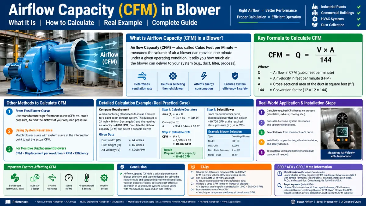
Airflow capacity, measured in CFM (Cubic Feet per Minute), is one of the most important specifications when selecting an industrial air blower. It tells you how much air a blower can move within one minute. However, choosing a blower only by CFM is not sufficient. A proper industrial blower selection also requires static pressure, duct dimensions, air velocity, temperature, application requirements, and motor power.
This comprehensive guide explains what CFM means, how to calculate blower airflow capacity, which formulas engineers use, and how to select a blower for a real company or factory installation.
CFM stands for Cubic Feet per Minute. It is a unit used to measure the volume of air moved by a blower in one minute.
Simple Definition :
If a blower has a capacity of 1,000 CFM, it means the blower is designed to move approximately 1,000 cubic feet of air per minute under specified operating conditions.
For example:
| Blower AirFlow Capacity | Air Moved Per Minute |
|---|---|
| 500 CFM | 500 cubic feet |
| 1,000 CFM | 1,000 cubic feet |
| 5,000 CFM | 5,000 cubic feet |
| 10,000 CFM | 10,000 cubic feet |
In metric units, industrial blowers are also commonly rated in:
The standard conversion is:
AirFlow Capacity (CFM) to m³/hr Formula:
1 CFM = 1.699 m³/hr
Therefore:
Where CMH means Cubic Meters per Hour.
Example:
A 2,000 CFM blower:
Therefore, a 2,000 CFM blower moves approximately 3,398 m³/hr.
This conversion is particularly useful in India, where blower manufacturers commonly provide capacity in m³/hr while American manufacturers often use AirFlow Capacity (CFM).
AirFlow Capacity determines whether a blower can deliver enough air for a particular industrial application. An incorrectly selected blower can cause:
For example, suppose a factory requires 5,000 CFM for proper ventilation but installs a blower capable of only 2,000 CFM.
The result may be:
Similarly, selecting a 15,000 CFM blower for a small workshop may create unnecessary electricity costs and excessive air velocity.
Therefore:
The correct blower is not necessarily the blower with the highest AirFlow Capacity (CFM). It is the blower that provides the required airflow at the required pressure.
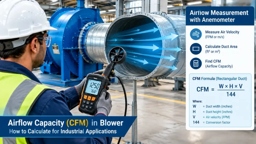
Every industrial blower selection should begin with two fundamental questions:
Question 1: How Much Airflow Is Required?
This is measured in CFM.
Question 2: How Much Pressure Is Required?
This is measured in:
CFM tells us how much air must move. Pressure tells us how difficult it is to move that air through the system.
Airflow moves air. Pressure overcomes resistance. A blower may have a high CFM rating but fail in an application requiring high static pressure.
For example:
| Application | Typical Requirement |
|---|---|
| General ventilation | High CFM, low pressure |
| Furnace combustion | Controlled CFM, moderate pressure |
| Dust collection | High CFM, high pressure |
| Pneumatic conveying | Moderate CFM, high pressure |
| Wastewater aeration | Continuous CFM, high pressure |
| Cooling machinery | High CFM, moderate pressure |
Industrial blower selection must therefore consider both airflow and system resistance.
There is no single formula suitable for every blower application. Engineers use different formulas depending on whether airflow is determined by:
Let’s examine each method in detail.
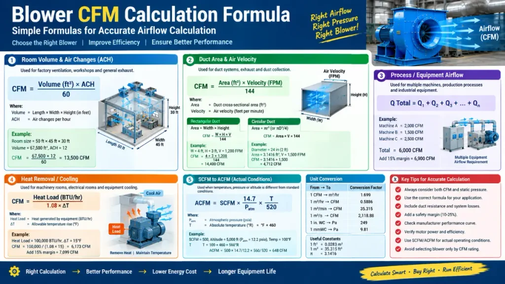
This is one of the most commonly used formulas for factory ventilation and industrial workshops.
Formula:
Where:
What Is ACH?
ACH stands for Air Changes per Hour. It indicates how many times the total air volume of a room should be replaced every hour.
For example:
Higher ACH is generally required for industrial environments with:
ACH requirements vary by application and ventilation design standards. Always verify the final design with a qualified HVAC or mechanical engineer.
Suppose a manufacturing company has the following room:
This is a realistic example for a medium-sized industrial workshop.
The total room volume is: 67,500 Cubic Feet
Suppose the factory requires 12 air changes per hour for general industrial ventilation.
Using the formula:
Required Airflow = 13,500 CFM
This means the factory requires approximately 13,500 CFM of ventilation airflow to replace the entire room air volume twelve times per hour.
Industrial systems should generally include a design margin for:
A commonly used preliminary margin is 15–20%, subject to engineering requirements.
Assume 15% margin:
Recommended Design Capacity = Approximately 15,500 CFM
This does not automatically mean one 15,500 CFM blower must be installed. The final selection depends on static pressure, duct arrangement, noise requirements, and the type of blower.
For example, the company could install:
This formula is extremely useful when designing or evaluating duct systems.
Formula:
Where:
Suppose a factory has a circular duct with:
Diameter = 24 inches
Convert inches into feet:
Radius:
Formula:
Assume required air velocity is 1,500 FPM.
Required Airflow = Approximately 4,712 CFM
Therefore, a blower capable of delivering approximately 4,700–5,000 CFM at the required static pressure would be considered for this duct.
For rectangular ducts:
If dimensions are in feet:
Suppose a rectangular exhaust duct has:
Required Airflow = 14,400 CFM
This method is commonly used in:
In India, industrial blower capacity is frequently specified in CMH.
Formula:
Where:
Suppose:
Convert to CFM:
Required Airflow = Approximately 30,500 CFM
Many industrial applications cannot be sized using room volume alone.
Examples include:
In these applications, airflow depends on process requirements.
Basic Formula:
Where each Q represents the airflow requirement of individual equipment.
A manufacturing company operates three machines requiring air supply:
| Machine | Required Airflow |
|---|---|
| Machine A | 2,000 CFM |
| Machine B | 1,500 CFM |
| Machine C | 2,500 CFM |
Total airflow:
Add 15% design margin:
Recommended Blower Capacity = Approximately 6,900 CFM
This approach is more accurate than simply calculating room ventilation when the blower supplies process equipment.
In factories, blowers are often installed to remove heat generated by:
Airflow required for cooling depends on heat load and allowable temperature rise.
A commonly used engineering relationship is:
Where:
Suppose a machine room generates:
Heat load = 100,000 BTU/hr
Maximum allowable temperature rise = 15°F
Required Cooling Airflow = Approximately 6,173 CFM
With a 15% design margin:
Selected Blower Capacity = Approximately 7,100 CFM
This formula is particularly useful for electrical rooms, machinery rooms, industrial workshops, and equipment cooling applications.
One of the most important technical concepts in blower selection is the difference between SCFM and ACFM.
SCFM – Standard Cubic Feet per Minute
SCFM represents airflow at standardized atmospheric conditions. It is commonly used for:
ACFM – Actual Cubic Feet per Minute
ACFM represents actual airflow under real operating conditions. It considers:
For blower selection, actual operating conditions are important because air density changes with temperature and pressure.
Manufacturers often provide blower performance curves based on specific inlet conditions.
Where:
Suppose a process requires:
Convert temperature:
Apply formula:
Required Actual Airflow = 648 ACFM
This demonstrates why SCFM and ACFM cannot always be used interchangeably.
For preliminary estimation, engineers sometimes use fan affinity laws.
Airflow is approximately proportional to rotational speed and the cube of impeller diameter for geometrically similar fans.
Simplified Relationship :
Where:
For two similar blowers:
This is useful when comparing two similar centrifugal blowers.
Existing blower:
New required speed = 1,750 RPM
Assuming the same impeller diameter:
Estimated New Capacity = 6,034 CFM
However, increasing RPM also affects pressure and power consumption significantly.
Therefore, fan laws should only be used for preliminary calculations and verified using manufacturer performance curves.
CFM alone does not determine motor size. The motor must provide sufficient power to overcome airflow resistance. A simplified air power relationship is:
For SI units:
Where:
Suppose:
1 CFM = 0.0004719 m³/s
After considering motor efficiency, starting conditions, and safety margin, a standard motor may be selected in the range of 15 kW, depending on the manufacturer’s fan curve and operating point.
Never select a motor solely from a simplified formula. Always verify:
Let’s consider a real-world industrial installation scenario.
A manufacturing company wants to install an industrial centrifugal blower for factory ventilation.
General industrial ventilation and heat removal.
12 ACH.
Assume 15%:
Required airflow: 15,525 CFM
Suppose duct calculations indicate:
| Component | Pressure Loss |
|---|---|
| Main Duct Friction | 250 Pa |
| Elbows and Bends | 180 Pa |
| Filters | 300 Pa |
| Outlet Grille | 120 Pa |
| Safety Allowance | 150 Pa |
| Total | 1,000 Pa |
Therefore:
Required Static Pressure = 1,000 Pa
The required operating point is:
| Parameter | Requirement |
|---|---|
| Airflow | 15,525 CFM |
| Static Pressure | 1,000 Pa |
| Application | Factory ventilation |
| Operation | Continuous |
| Motor | Industrial duty |
| Control | VFD preferred |
The blower should be selected from a manufacturer’s performance curve where:
Airflow = Approximately 15,500 CFM at 1,000 Pa static pressure.
A blower rated at 15,500 CFM free air may not deliver this airflow once duct resistance is connected.
This distinction is extremely important.
Many manufacturers advertise blower capacity under free-air conditions.
The blower discharges air into an open area with minimal resistance.
The blower operates through:
Installed airflow is often lower than free-air airflow because system resistance reduces actual performance.
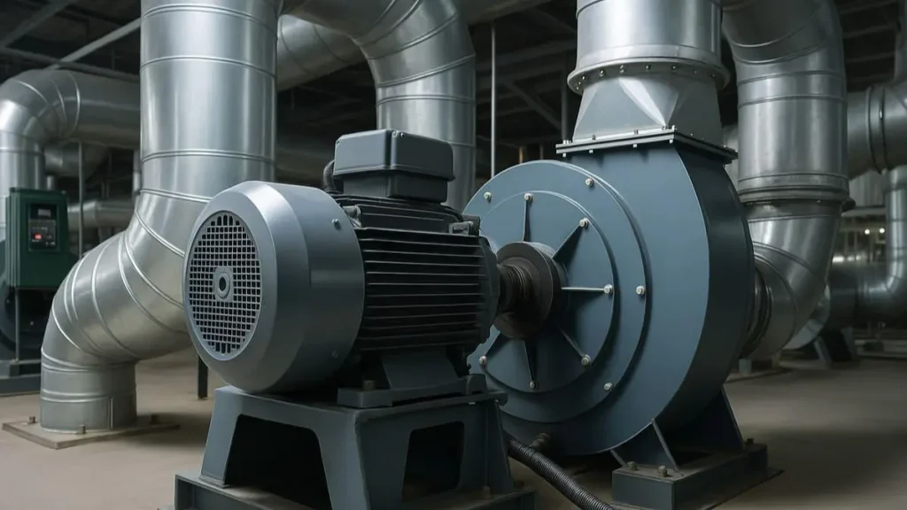
Therefore, when purchasing an industrial blower, always ask the manufacturer:
What is the airflow at the required static pressure?
Do not simply ask:
How many CFM is the blower?
The correct technical question is:
What is the blower’s CFM at my required pressure?
Different industries require different airflow calculations.
| Application | Primary Calculation Method |
|---|---|
| Factory Ventilation | Room Volume × ACH |
| Dust Collection | Duct Area × Velocity |
| Furnace Combustion | Fuel Requirement / Stoichiometric Air |
| Machinery Cooling | Heat Load Formula |
| Pneumatic Conveying | Material Flow and Air Velocity |
| Wastewater Aeration | Oxygen Demand |
| Drying Systems | Moisture Removal Requirement |
| Welding Fume Extraction | Capture Velocity |
| Chemical Exhaust | Process Emission Rate |
| Warehouse Ventilation | ACH Method |
Combustion air is a specialized application. A furnace requires sufficient oxygen for complete fuel combustion. Airflow depends on:
For example, natural gas burners require a calculated quantity of combustion air based on fuel consumption.
A typical engineering approach is:
For combustion systems, the blower must be selected based on burner manufacturer’s combustion air requirements and pressure specifications.
Combustion blower sizing should not be based only on room volume or general ventilation formulas.
Dust collection systems require sufficient air velocity to capture and transport particles.
The formula is:
For dusty industrial environments, required transport velocity depends on the material.
Examples include:
If velocity is too low:
If velocity is too high:
Therefore, dust collection blower selection requires both airflow and pressure calculations.
Use the following step-by-step engineering method.
Determine whether the blower is required for:
Choose the appropriate formula:
Calculate resistance from:
Typical preliminary design allowance:
10–25%, depending on engineering requirements.
Useful conversions:
| Unit | Conversion |
|---|---|
| 1 CFM | 1.699 m³/hr |
| 1 m³/hr | 0.5886 CFM |
| 1 m³/min | 35.315 CFM |
| 1 m³/s | 2,118.88 CFM |
| 1 in WC | Approximately 249 Pa |
| 1 mmWC | Approximately 9.81 Pa |
Select the blower at the intersection of:
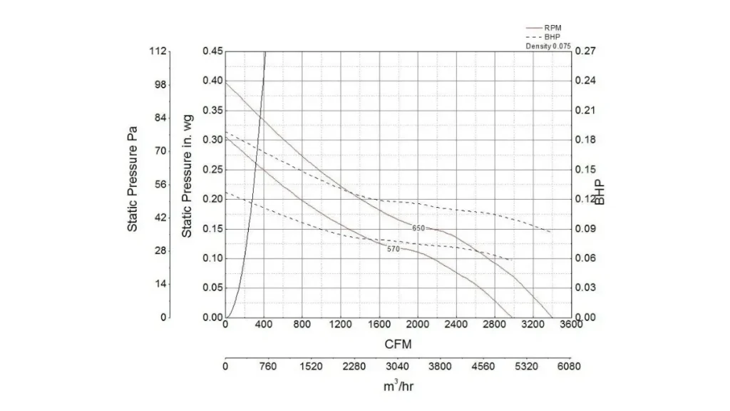
Check:
There is no universal answer because CFM depends on the application.
| Application | Approximate Airflow Range |
|---|---|
| Small Workshop Ventilation | 500–3,000 CFM |
| Medium Factory | 3,000–15,000 CFM |
| Large Industrial Plant | 15,000–100,000+ CFM |
| Small Machine Cooling | 300–1,500 CFM |
| Furnace Combustion | Application-specific |
| Dust Extraction | 2,000–20,000+ CFM |
| Industrial Drying | 5,000–50,000+ CFM |
These are general planning ranges only. Actual requirements must be calculated based on engineering conditions.
Best suited for:
Centrifugal blowers generally provide higher pressure capability.
Best suited for:
Axial blowers can move large volumes of air efficiently but may not be suitable for high-resistance duct systems.
| Feature | Centrifugal Blower | Axial Blower |
|---|---|---|
| Airflow Capacity | Moderate to Very High | Very High |
| Static Pressure | High | Low to Moderate |
| Duct Resistance | Handles High Resistance | Limited Compared with Centrifugal |
| Application | Dust Collection, Exhaust | Ventilation, Cooling |
| Efficiency | Depends on Design | Excellent at Low Pressure |
| Mistake 1: Selecting Blower Only by CFM | Ignoring static pressure can result in poor performance. |
| Mistake 2: Using Free-Air Capacity | Free-air ratings may not represent actual installed airflow. |
| Mistake 3: Ignoring Duct Size | A blower cannot efficiently deliver required airflow through an undersized duct. |
| Mistake 4: Forgetting Filters | Dirty filters increase system resistance and reduce airflow. |
| Mistake 5: No Safety Margin | Future expansion and system aging can reduce performance. |
| Mistake 6: Confusing SCFM and ACFM | Temperature and altitude affect actual air volume. |
| Mistake 7: Oversizing the Blower | An oversized blower wastes electricity and may create excessive noise. |
| Mistake 8: Undersizing the Motor | Insufficient motor power causes overheating and premature failure. |
Before contacting a blower manufacturer, prepare the following information.
| Parameter | Required Information |
|---|---|
| Application | Ventilation / Cooling / Exhaust |
| Required Airflow | CFM or m³/hr |
| Static Pressure | Pa / mmWC |
| Temperature | °C or °F |
| Gas Type | Air / Hot Air / Chemical Gas |
| Dust Load | Clean / Dusty / Heavy Dust |
| Operating Hours | Intermittent / Continuous |
| Power Supply | 230V / 415V / 460V |
| Installation Location | Indoor / Outdoor |
| Duct Size | Diameter or Width × Height |
| Motor Control | Direct Start / VFD |
| Noise Requirement | Yes / No |
This information allows manufacturers to provide accurate blower recommendations.
Airflow capacity, measured in CFM, is the foundation of proper industrial blower selection. It determines how much air a blower can move, but CFM alone does not guarantee correct performance.
The most important formulas are:
For a real factory installation, engineers should calculate airflow requirements, static pressure, duct resistance, temperature, and motor power before purchasing a blower.
The best industrial blower is not the one with the highest CFM rating—it is the one that delivers the required airflow at the required pressure efficiently and reliably.
CFM stands for Cubic Feet per Minute. It measures the volume of air a blower can move in one minute.
The most common formula for room ventilation is: CFM=RoomVolume×ACH60CFM = \frac{Room Volume \times ACH}{60}For duct systems: CFM=DuctArea×AirVelocityCFM = Duct Area \times Air Velocity
CFM is an imperial airflow unit commonly used in the USA. m³/hr is a metric airflow unit commonly used in India and other countries. 1 CFM = 1.699 m³/hr.
No. Higher CFM is not automatically better. The blower must match the required airflow and static pressure of the system.
It depends on factory size, air changes required, heat generation, process requirements, and ventilation design.
Use:CFM=Length×Width×Height×ACH60CFM = \frac{Length \times Width \times Height \times ACH}{60}
SCFM is airflow at standard conditions. ACFM is airflow at actual operating conditions considering temperature and pressure.
Yes. Undersized ducts create higher resistance and reduce actual airflow.
A preliminary design margin of 10–25% is commonly considered depending on the application and engineering requirements.
Motor power depends on airflow, pressure, blower efficiency, and motor efficiency. It should be verified using the manufacturer’s performance curve.
Axial blowers are generally suitable for high-volume, low-pressure ventilation. Centrifugal blowers are more suitable for high-pressure ducted systems.
Room size provides a starting point for ventilation airflow calculation, but final selection also requires static pressure and system resistance calculations.
References and Further Reading :

Welcome! I am a dedicated entrepreneur running an industrial affiliate product website, helping businesses and professionals find the best tools, equipment, and resources for their needs. With a passion for industrial products and a keen eye for quality, I curate and recommend top-performing items that enhance efficiency and reliability.
Through my platform, I aim to simplify the buying process by providing valuable insights, expert reviews, and trusted affiliate links to high-quality industrial products. Whether you’re looking for the latest machinery, tools, or safety gear, I strive to connect you with the best solutions available.
Thank you for visiting, and I look forward to helping you make informed purchasing decisions!
