Our Location
Killa-Pardi, Dist. Valsad, 396125

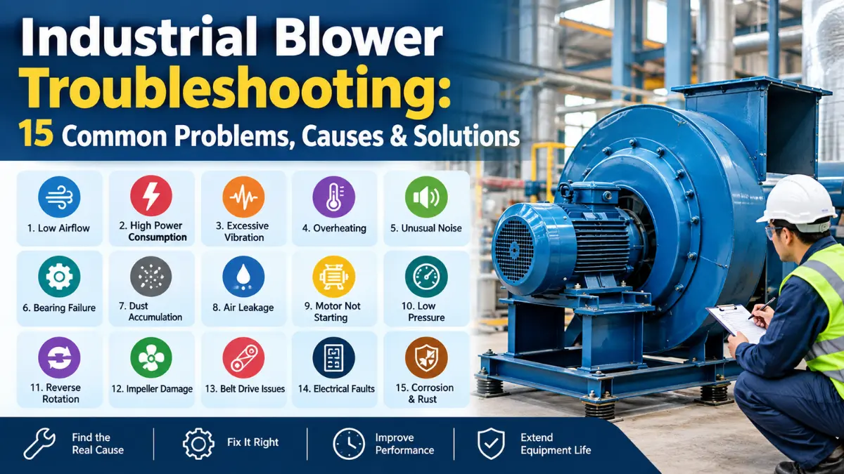
Industrial blowers are critical in factories, warehouses, processing plants, HVAC systems, dust-collection systems, furnaces, drying equipment and exhaust applications. When a blower starts delivering less air, consuming more electricity, vibrating, overheating or making unusual noise, the problem should be investigated before it develops into an expensive failure.
Industrial blower troubleshooting is the process of identifying the difference between the blower’s expected operating condition and its actual performance, then finding the root cause and correcting it. In practical maintenance work, the most useful measurements are airflow (CFM), static pressure (in. w.g. or Pa), motor current (A), speed (RPM), temperature, vibration and power (kW).
For U.S. industrial readers, this article uses commonly used units such as CFM, inches of water gauge (in. w.g.), HP, RPM and °F, while metric units are included where useful. OSHA also emphasizes maintaining adequate airflow and periodically checking pressure drop in exhaust ventilation systems.
Industrial blower troubleshooting means systematically finding the reason a blower is not operating as expected.
For example, suppose a centrifugal blower was designed to deliver 10,000 CFM at 6 in. w.g., but the system is now producing only 7,500 CFM. Simply increasing the motor speed may not solve the problem. The cause could be a clogged filter, blocked duct, slipping belt, incorrect rotation, dirty impeller or increased system resistance.
A good troubleshooting process therefore compares actual performance with design or rated performance.
A practical sequence is:
Safety → Motor → RPM → Airflow → Static Pressure → Filter → Duct → Impeller → Bearings → Belt/Coupling → VFD
AMCA’s field-performance guidance covers measurement of fan systems used for industrial process, exhaust, drying, air cleaning and dust collection applications.
Low airflow is one of the most common blower complaints. If a system that normally produces 10,000 CFM suddenly produces 8,000 CFM, the first step should be to determine whether the problem is at the blower or somewhere in the connected system.
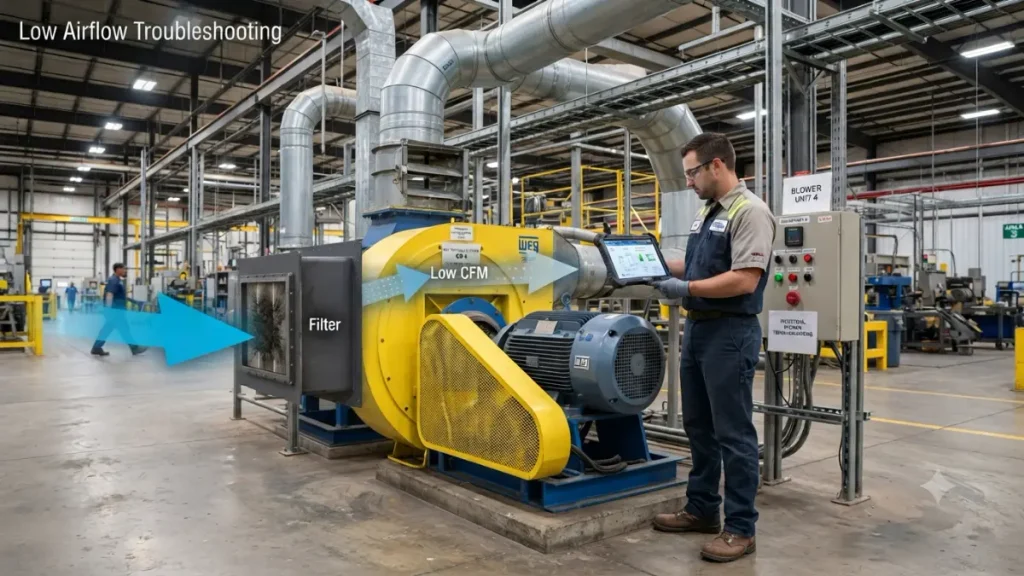
For example, if the blower speed has fallen from 1,800 RPM to 1,600 RPM, the airflow can fall substantially. Under simplified fan-affinity relationships, airflow varies approximately with speed:
Q₂ / Q₁ = N₂ / N₁
So, if the original airflow was 10,000 CFM at 1,800 RPM:
Q₂ = 10,000 × (1,600 / 1,800)
Q₂ ≈ 8,889 CFM
This is an illustrative calculation; actual system performance depends on the fan curve and system curve. AMCA identifies airflow, pressure and power as interconnected fan-performance parameters.
OSHA’s ventilation guidance specifically identifies reversed fan rotation, low RPM, slipping belts, clogged fan wheels, clogged ductwork, closed dampers and clogged air-cleaning equipment as possible causes of low airflow.
Start by checking the filter, ductwork, damper position and impeller. Then verify motor RPM and rotation direction.
Important : Do not assume that increasing motor power will automatically solve low airflow. The actual problem may be excessive system resistance.
A blower can consume excessive electrical power when it is operating at a higher load than expected. Typical causes include:
A simplified relationship between air power and airflow is: Air Power ≈ Q × ΔP
where Q is airflow and ΔP is pressure difference.
For a practical example, assume:
The approximate air power is:
Air Power (HP) ≈ CFM × Pressure / (6,356 × Efficiency)
≈ 10,000 × 6 / (6,356 × 0.70)
≈ 13.5 HP
This is an engineering estimate, not a substitute for the manufacturer’s fan curve or measured electrical input. The important point is that CFM alone cannot tell you how much power a blower requires. Pressure and efficiency matter too.
Excessive vibration is an important warning sign because it can indicate mechanical imbalance or alignment problems. Common causes include:
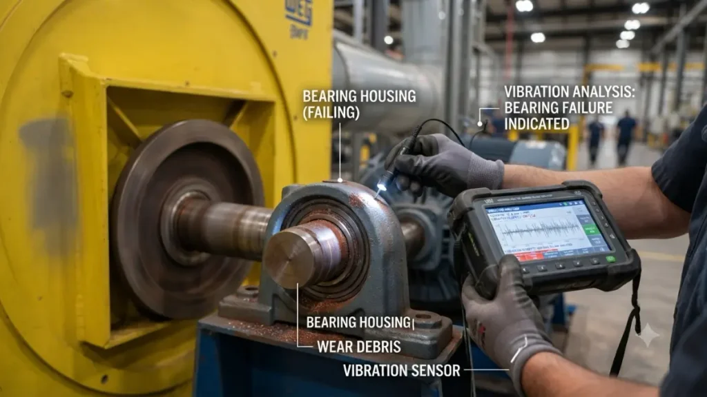
For example, if dust accumulates unevenly on a centrifugal impeller, the wheel may become unbalanced. At operating speed, even a relatively small imbalance can produce significant centrifugal forces.
Do not diagnose vibration only by touching the machine. A vibration meter or vibration-analysis system provides much better information. AMCA’s fan application material specifically distinguishes aerodynamic performance from mechanical issues such as noise and vibration.
Check alignment, foundation bolts, bearings, coupling and impeller balance. For critical industrial equipment, vibration should be measured with an appropriate vibration meter rather than judged only by touch.
Practical rule: If vibration is increasing over time, treat the trend as more important than a single isolated reading.
Blower overheating can originate from either the motor or the mechanical components.
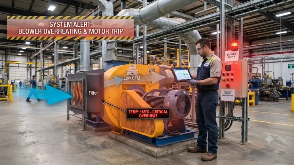
Common causes include:
Suppose a blower motor normally operates at 22 A but gradually increases to 27 A under the same process conditions. That change deserves investigation. Possible explanations include increased system load, mechanical friction, bearing deterioration or an electrical problem. Do not simply increase the overload setting to stop nuisance trips. The correct approach is to identify why the motor current has increased.
Check motor current, bearing temperature, ventilation and operating pressure. Compare actual operating conditions with the manufacturer’s rated specifications.
Repeated motor trips are a warning that the motor or blower is operating outside its normal condition. Possible causes include:
For example, if motor’s rated full-load current is 30 A & measured current is consistently around 35 A, the maintenance team should investigate the load rather than repeatedly resetting the protection device.
Never repeatedly reset a tripped motor without finding the cause. For maintenance work, follow the equipment manufacturer’s procedures and applicable electrical safety requirements.
Noise is often one of the earliest signs that something has changed.
| Noise | Possible Cause |
|---|---|
| Grinding | Bearing wear |
| Rattling | Loose component |
| Whistling | Air leakage |
| Screeching | Belt slipping |
| Humming | Electrical issue |
| Knocking | Impeller or mechanical contact |
| High-pitched noise | Bearing/RPM issue |
| Pulsating sound | Unstable airflow/system condition |
For example, a screeching sound during startup may point toward belt slip, while a continuous grinding sound may indicate bearing deterioration.
Noise should be investigated together with vibration, temperature and operating conditions rather than used as the only diagnostic measurement.
Bearings support rotating components and are essential for reliable blower operation. Common warning signs include:
One useful maintenance strategy is trend monitoring.
For example:
| Week | Bearing Temperature | Vibration |
|---|---|---|
| Week 1 | 125°F | 2.1 mm/s |
| Week 2 | 131°F | 2.5 mm/s |
| Week 3 | 139°F | 3.0 mm/s |
| Week 4 | 148°F | 3.8 mm/s |
These numbers are illustrative maintenance data, not universal alarm limits. The important observation is the upward trend.
Actual alarm and shutdown limits should come from the equipment manufacturer, bearing manufacturer or applicable vibration standard.
A blower must overcome the resistance created by ducts, filters, dampers, bends, equipment and other components. If system resistance becomes higher than the blower’s design point, airflow can decrease and power consumption may change.
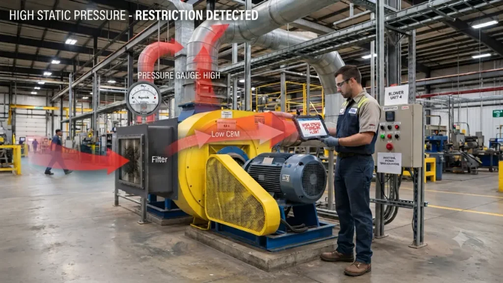
Resistance can come from:
Consider a dust-collection system designed for 8,000 CFM at 5 in. w.g. If a filter becomes heavily loaded and pressure drop increases, the blower may no longer deliver the required airflow.
OSHA’s ventilation requirements recognize pressure losses from hoods, branch ducts, main ducts, filters and other mechanical equipment as components of system static pressure. OSHA also calls for periodic pressure-drop checks in exhaust systems.
This is why CFM and static pressure must be evaluated together.
When actual CFM is lower than the expected value, use a structured diagnostic approach rather than immediately changing the motor. Check:
1. Filter → 2. Damper → 3. Duct → 4. Impeller → 5. RPM → 6. Rotation → 7. Leakage → 8. Static pressure
This combination strongly suggests that system resistance or another system-side problem deserves investigation. A blower performance curve can then be used to determine where the actual operating point lies.
AMCA describes a fan curve as the relationship between pressure and volume flow at a given fan speed.
The impeller is the rotating component that transfers energy to the air. Dust, fibers, process material or foreign objects can accumulate on the impeller. Uneven buildup can also disturb balance.
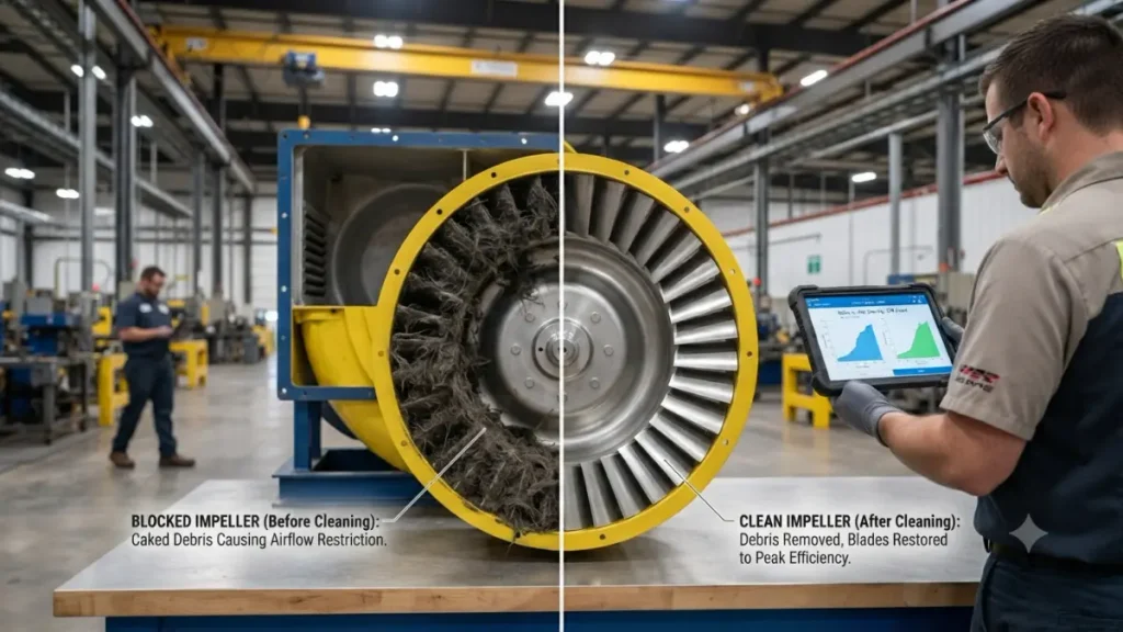
Typical symptoms include:
For example, a dust-collection blower handling fine particulate may gradually accumulate material on the wheel. The blower can continue running while its performance slowly deteriorates.
During inspection, check for material buildup, cracks, corrosion, erosion, rubbing marks and imbalance. Always isolate and lock out equipment before entering or servicing a blower housing.
A clogged filter increases system resistance. As the pressure drop across the filter increases, the blower may struggle to maintain the required airflow.
A differential-pressure indicator can help identify when filter cleaning or replacement is required. A dirty filter creates additional pressure drop.
Imagine a system where the clean-filter pressure drop is: 1.0 in. w.g.
After extended operation it increases to: 3.0 in. w.g.
The additional 2.0 in. w.g. represents a substantial increase in system resistance. The blower may respond with reduced airflow, changed operating point and potentially different power consumption. This is why pressure-drop monitoring is more useful than replacing filters only according to a fixed calendar.
OSHA’s ventilation guidance recommends periodic inspection and monitoring of pressure drop across air-cleaning equipment.
Belt-driven blowers require correct belt tension and pulley alignment. A belt that is too loose can slip and reduce blower speed. A belt that is excessively tight can increase bearing loading.
Do not estimate belt tension simply by pressing the belt with your finger. Follow the belt manufacturer’s recommended tension method.
A Variable Frequency Drive (VFD) controls motor speed by changing the electrical frequency supplied to the motor.
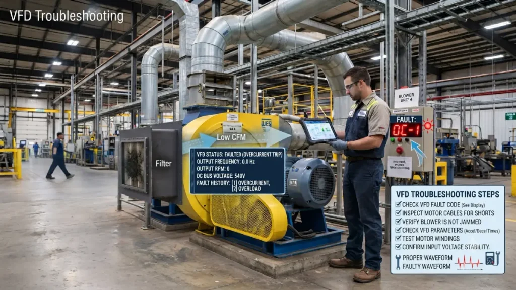
Common mistakes include:
For example, if a motor is designed for 60 Hz operation but the control system is incorrectly configured, the blower may not operate at the intended speed.
Fan affinity relationships are especially important when speed changes. In simplified form:
Therefore, a relatively small speed increase can produce a much larger increase in theoretical power demand. AMCA describes these relationships as fan affinity laws and notes that actual high-pressure applications may require additional considerations.
Preventive maintenance is generally more effective than waiting for a blower to fail.
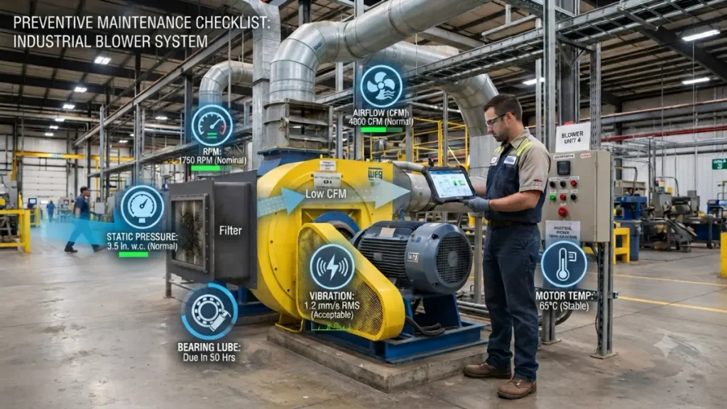
A practical inspection program can include:
| Component | What to Check |
|---|---|
| Motor | Current, temperature, vibration |
| Bearings | Temperature, noise, lubrication |
| Impeller | Dirt, cracks, erosion, balance |
| Belts | Wear, tension, alignment |
| Coupling | Alignment and condition |
| Filter | Pressure drop |
| Duct | Blockage and leakage |
| Damper | Position and operation |
| Foundation | Loose bolts |
| VFD | Fault codes and parameters |
| Airflow | CFM |
| Pressure | Static/total pressure |
OSHA’s technical guidance describes preventive maintenance as an important part of ventilation-system control and gives examples of daily, weekly and monthly inspection activities.
For U.S. industrial facilities, maintenance procedures should also follow applicable OSHA requirements and the equipment manufacturer’s instructions. AMCA Publication 410-25 provides recommended safety practices for installation, operation and maintenance of industrial and commercial fans.
| Problem | Likely Cause | What to Check | Corrective Action |
|---|---|---|---|
| Low CFM | Filter/duct restriction | Pressure drop | Clean/repair system |
| Low RPM | Belt/VFD/motor | RPM | Correct speed |
| High power | High pressure/load | kW + pressure | Find system resistance |
| High vibration | Imbalance | Vibration | Inspect/balance |
| Bearing noise | Bearing wear | Noise/temp/vibration | Inspect bearing |
| Motor overheating | Overload | Current | Check load |
| Motor trips | Electrical/mechanical | Current + fault code | Find root cause |
| Belt slipping | Incorrect tension | Belt condition | Correct tension |
| High static pressure | Restriction | Pressure | Inspect duct/filter |
| Impeller buildup | Dust/material | Visual inspection | Clean safely |
| VFD fault | Incorrect parameters | Drive settings | Verify motor data |
| Unusual noise | Mechanical issue | Sound + vibration | Inspect components |
When a industrial blower has a performance problem, avoid changing multiple parameters at the same time.
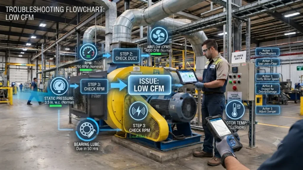
Use this sequence:
1. Check safety → 2. Check motor → 3. Check RPM → 4. Check airflow → 5. Check pressure → 6. Check filter → 7. Check duct → 8. Check impeller → 9. Check bearings → 10. Check VFD
This makes it easier to identify the actual root cause.
Consider a manufacturing plant with a centrifugal exhaust blower. The original design condition is:
After several months, the operator reports that production-area exhaust has become weaker. The maintenance team records:
The wrong response would be to immediately install a larger motor.
The better approach is to investigate the filter and system resistance first. The increased pressure and reduced airflow indicate that the system is operating differently from the original design point. After cleaning/replacing the filter and inspecting the duct, the measurements should be taken again.
This illustrates an important maintenance principle: Do not treat the symptom before identifying the root cause.
OSHA’s ventilation guidance similarly emphasizes checking pressure drop and correcting restrictions when system performance changes.
For serious industrial troubleshooting, create a simple operating record.
| Parameter | Normal | Actual |
|---|---|---|
| Airflow | 10,000 CFM | 7,900 CFM |
| Static pressure | 6.0 in. w.g. | 8.0 in. w.g. |
| Speed | 1,800 RPM | 1,790 RPM |
| Motor current | 24 A | 28 A |
| Bearing temperature | 125°F | 145°F |
| Vibration | Baseline | Increasing |
The actual numbers above are illustrative, but this type of record is extremely useful. A maintenance technician can compare today’s readings with previous readings instead of relying on memory.
AMCA’s field-performance approach emphasizes measuring fan-system performance rather than relying only on nameplate or catalog information.
Industrial blower troubleshooting should be based on measured operating data rather than guesswork. When airflow decreases or power consumption increases, check the complete system—including the filter, ductwork, dampers, impeller, belts, bearings, motor and VFD. The most useful parameters to trend are:
CFM + Static Pressure + RPM + Motor Current + kW + Temperature + Vibration
For U.S. industrial applications, CFM and in. w.g. are common working units, while Pa and m³/h may also appear on international equipment documentation.
Most importantly, do not automatically increase motor size or blower speed when performance drops. First determine why the operating point has changed. A systematic troubleshooting process can reduce unnecessary energy use, prevent equipment damage and help avoid unplanned production downtime.
References:
- AMCA International — fan performance, affinity laws, field performance measurement and fan safety. (AMCA)
- OSHA — 29 CFR 1910.94 — industrial ventilation and exhaust-system requirements. (OSHA)
- OSHA — 29 CFR 1926.57 — ventilation requirements, airflow and static-pressure considerations. (OSHA)
- OSHA Technical Manual — ventilation-system maintenance and troubleshooting guidance. (OSHA)
- AMCA 202 / 203 resources — fan-system troubleshooting and field-performance measurement. (AMCA)
Industrial blower troubleshooting is the systematic process of identifying and correcting blower problems such as low airflow, high pressure, vibration, overheating, noise and excessive power consumption.
Common causes include clogged filters, blocked ducts, incorrect RPM, wrong rotation, impeller blockage, belt slipping and excessive system resistance.
High pressure, excessive RPM, mechanical friction, bearing problems, belt issues and inefficient operating conditions can increase power consumption.
The most common causes include impeller imbalance, misalignment, worn bearings, loose foundation bolts and shaft problems.
Motor overload, bearing friction, poor ventilation, high ambient temperature, electrical problems and excessive system resistance can cause overheating.
Repeated tripping can be caused by overload, voltage problems, phase imbalance, bearing problems, short circuits or incorrect protection settings.
First identify why airflow is low. Check the filter, duct, damper, impeller, motor RPM, rotation direction and system pressure before making changes.
Yes. A clogged filter increases pressure drop and system resistance, which can reduce the airflow delivered by the blower.
Common causes include inadequate lubrication, over-lubrication, contamination, misalignment, excessive belt tension, imbalance and excessive operating temperature.
No. CFM and static pressure should both be considered, along with temperature, gas properties, operating conditions, motor power and efficiency.
Yes, in suitable variable-airflow applications, reducing motor speed with a VFD can significantly reduce energy use. However, actual savings depend on the system and operating conditions.
Inspection frequency depends on operating hours, environment, blower type and manufacturer’s recommendations. Critical equipment generally requires more frequent condition monitoring.
Start with the filter, duct, damper, impeller, RPM and rotation direction. These are common sources of airflow problems.
Rapidly increasing vibration, bearing temperature, unusual mechanical noise or repeated motor trips should be treated as serious warning signs requiring prompt inspection.
A dirty filter increases system resistance and can alter the blower’s operating point. The resulting operating condition may increase mechanical or motor loading depending on the fan/system characteristics.
Low CFM can result from low RPM, incorrect rotation, clogged filters, blocked ducts, dirty impellers, closed dampers or excessive system resistance.
Yes. Under simplified fan-affinity relationships, power varies approximately with the cube of speed, so increasing RPM can significantly increase power demand.
Replace a bearing based on condition, manufacturer recommendations and inspection results. Increasing vibration, temperature, noise or shaft play can indicate deterioration.

Welcome! I am a dedicated entrepreneur running an industrial affiliate product website, helping businesses and professionals find the best tools, equipment, and resources for their needs. With a passion for industrial products and a keen eye for quality, I curate and recommend top-performing items that enhance efficiency and reliability.
Through my platform, I aim to simplify the buying process by providing valuable insights, expert reviews, and trusted affiliate links to high-quality industrial products. Whether you’re looking for the latest machinery, tools, or safety gear, I strive to connect you with the best solutions available.
Thank you for visiting, and I look forward to helping you make informed purchasing decisions!
