Our Location
Killa-Pardi, Dist. Valsad, 396125

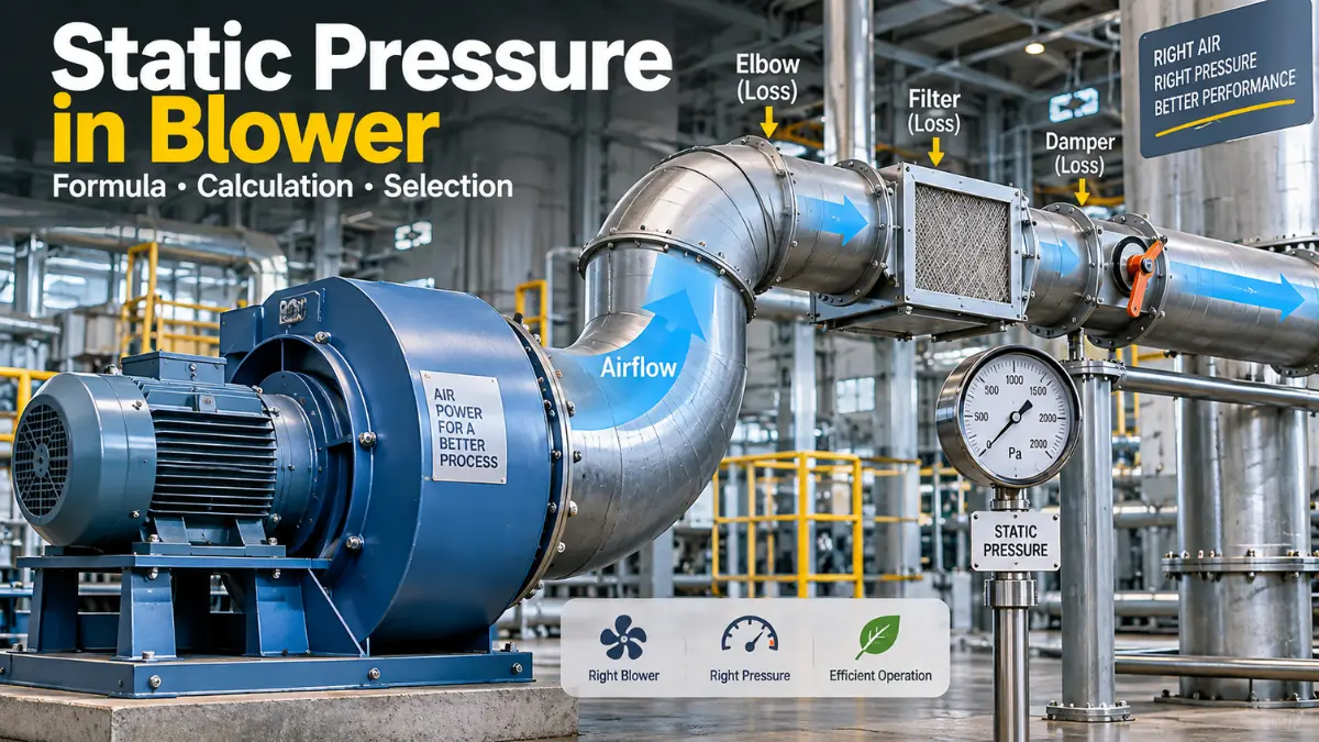
Static pressure in a blower means the pressure available to push air through a duct or industrial system and overcome resistance from filters, elbows, dampers, furnaces, burners, heat exchangers, and other equipment.
When selecting an industrial blower, two specifications are especially important:
A blower may have a very high airflow rating, but that does not automatically mean it can deliver the required air through a long duct, filter, damper, furnace, burner, heat exchanger, or other resistance. This is where static pressure becomes important. In simple words:
Static pressure is the pressure available from a blower to overcome resistance in the air-moving system.
The resistance may come from:
AMCA explains fan performance using airflow and pressure relationships and distinguishes fan static pressure, total pressure, and velocity pressure. For industrial applications in India and the USA, understanding static pressure is essential before purchasing a blower.
Static pressure is the pressure exerted by moving air against the walls of a duct or system, independent of the air’s velocity component.
For blower applications, it represents part of the pressure generated by the blower that is available to overcome system resistance. It is commonly expressed as:
For most industrial blower calculations, Pa, kPa, mmWC and in. WG are particularly useful.
Suppose a factory requires: 10,000 CFM of air
You find two blowers:
| Blower | Airflow | Static Pressure |
|---|---|---|
| A | 10,000 CFM | 1 in. WG |
| B | 10,000 CFM | 6 in. WG |
Both show the same airflow rating, but they are not necessarily suitable for the same system. If the factory’s duct and equipment resistance is 5 in. WG, blower A will not provide the required pressure at that operating condition. Blower B may be capable of meeting the duty point, subject to its actual performance curve.
This is why blower selection should be based on a duty point, not simply on the largest CFM number.
AMCA describes the duty point as the combination of required airflow and system pressure loss and explains that the operating point is established where the fan curve and system curve intersect.
This is one of the most important concepts in blower engineering. Air has both:
Together they form total pressure.
A simplified relationship is:
Where:
AMCA defines fan total pressure as the difference in total pressure between fan outlet and inlet, while fan static pressure uses outlet static pressure relative to inlet total pressure. Static-pressure rise is the difference between outlet and inlet static pressure.
Because a blower may produce pressure partly as:
If you use the wrong pressure value during selection, the blower may not perform as expected after installation.
Velocity pressure represents the pressure associated with air movement. The basic equation is:
Where:
At standard conditions, air density is approximately:
Example:
Suppose air velocity is:
Then:
So the velocity pressure is approximately: 86 Pa
AMCA provides a practical fan-curve example where 12,000 CFM at 5.0 in. WG static pressure had approximately 0.35 in. WG velocity pressure and 5.35 in. WG total pressure.
Indian factories commonly use mmWC/mmH₂O, while U.S. engineering documentation frequently uses in. WG. SI calculations generally use Pa or kPa.
Useful approximate conversions are:
Therefore:
Therefore:
Example :
Convert 500 mmWC to kPa:
Therefore: 500 mmWC ≈ 4.91 kPa
A blower does not normally work against only one resistance. The total system resistance can include:
| 1. Straight duct friction | Air loses pressure while traveling through ductwork. |
| 2. Elbows | Every bend produces additional pressure loss. |
| 3. Dampers | Partially closed dampers can create significant resistance. |
| 4. Filters | Dirty filters can have considerably higher pressure drop than clean filters. |
| 5. Heat exchangers | Air passing through tubes, fins or passages creates resistance. |
| 6. Furnace or burner | Combustion systems may require a specific pressure at the burner or furnace inlet. |
| 7. Cyclones and scrubbers | Industrial pollution-control equipment can create substantial pressure losses. |
| 8. Silencers | Acoustic treatment can add pressure drop. |
| 9. Transitions | Sudden changes in duct size can create additional losses. |
The blower must provide sufficient pressure to overcome these losses at the required airflow.
The first engineering step is to calculate the pressure loss of the complete system. A simplified system calculation is:
For example:
| Component | Pressure Loss |
|---|---|
| Straight duct | 250 Pa |
| Elbows | 180 Pa |
| Damper | 120 Pa |
| Filter | 300 Pa |
| Heat exchanger | 250 Pa |
| Burner/process equipment | 200 Pa |
| Safety margin | 150 Pa |
| Total | 1,450 Pa |
Required blower pressure:
In mmWC:
So the approximate requirement is: 148 mmWC
or:
Therefore: ≈ 5.8 in. WG
For detailed duct design, one commonly used approach is the Darcy-Weisbach equation:
Where:
For fittings, a simplified loss equation is:
Where:
This is why increasing airflow can dramatically increase pressure loss.
For many systems, pressure loss approximately follows:
where is airflow.
For example, suppose a duct system requires: 1,000 Pa at 10,000 CFM
If airflow increases by 20%:
Then approximate pressure requirement becomes:
So a 20% increase in airflow can increase system resistance by approximately 44%, assuming the same system configuration and the square-law relationship.
AMCA describes the system curve as generally varying with the square of the flow ratio.
Before calculating velocity pressure, calculate duct velocity.
The basic formula is:
Where:
Suppose:
Convert to m³/s:
Suppose duct area:
Then:
The approximate air velocity is: 11.1 m/s
Using:
Assume:
and:
Then:
Therefore: Velocity pressure ≈ 74 Pa
This illustrates why both static and velocity pressure should be understood when reading blower performance data.
Once airflow and pressure are known, approximate air power can be calculated using:
Where:
Actual shaft or electrical power will be higher because the blower and motor are not 100% efficient. Therefore:
Where:
If motor efficiency is also included:
Suppose a factory needs: 10,000 m³/h at: 2,000 Pa
Assume blower efficiency: 75%
So the theoretical shaft power requirement is approximately: 7.4 kW
The actual motor selection must then consider motor efficiency, starting conditions, service factor, operating range and manufacturer recommendations.
For U.S. units, a commonly used approximate fan power relationship is:
Where:
Suppose:
Then:
So the calculated shaft requirement is approximately: 11.8 HP
This is an engineering calculation, not a substitute for the manufacturer’s certified fan selection.
A particularly useful real-world published example comes from the Air Movement and Control Association International (AMCA).
AMCA presents a fan-selection example based on:
AMCA explains how the point is located on a fan performance curve and how the corresponding pressure and other performance values are interpreted.
The example also shows approximately:
This is an excellent demonstration of why 12,000 CFM alone is not enough information. The pressure requirement must also be known.
A useful manufacturer reference is Atlas Copco’s industrial blower range.
For example, Atlas Copco publishes the following range for its ZB VSD+ turbo blower:
Its ZHA single-stage centrifugal blower range is published at:
These are published product-range specifications, not a guarantee that every combination of flow, pressure and motor power is available from one model.
That distinction is extremely important when purchasing industrial equipment.
Let’s take a theoretical duty point for illustration:
Convert pressure:
Convert airflow:
or:
Assume overall blower efficiency of 80% for illustration:
So approximately: 556 kW shaft power
would be indicated by this simplified calculation.
Atlas Copco’s published ZHA range includes airflow from 7,000 to 32,000 m³/h, pressure from 0.3 to 1.2 bar(g), and installed motor power from 250 to 1,000 kW.
However, this calculation does not mean a particular ZHA model is selected. Final selection must use the manufacturer’s actual performance curve, efficiency, inlet conditions, temperature, pressure definition and operating point.
Consider a furnace combustion-air system.
Required airflow: 15,000 m³/h
Estimated system resistance:
| Component | Pressure Loss |
|---|---|
| Intake filter | 250 Pa |
| Inlet duct | 150 Pa |
| Elbows | 120 Pa |
| Damper | 100 Pa |
| Main duct | 300 Pa |
| Furnace entry | 350 Pa |
| Burner/process resistance | 400 Pa |
| Total | 1,670 Pa |
Add 10% engineering margin:
Convert to mmWC:
So the approximate design requirement becomes: 15,000 m³/h at 187 mmWC
or:
Therefore: ≈ 7.4 in. WG
This is the type of duty point that should be given to a blower supplier.
A common mistake is:
“I need 10,000 CFM, so I will buy a 10,000 CFM blower.”
This is incomplete. Instead, specify:
10,000 CFM at X in. WG static pressure
For example: 10,000 CFM @ 6 in. WG
This gives the supplier a much more useful duty point. The blower should then be checked against:
A typical blower curve has:
| X-axis | Airflow: CFM m³/h m³/s |
| Y-axis | Pressure: Pa kPa mmWC in. WG |
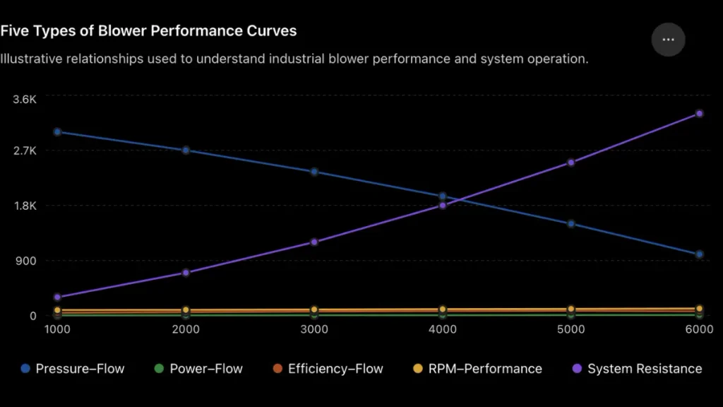
For a technical article, I recommend showing these as separate graphs, because pressure, power, efficiency, RPM, and system resistance have different units and scales.
To find the operating point:
AMCA explains that the fan curve represents the relationship between airflow and pressure and that the operating point is determined by the interaction between the fan curve and system curve.
Fan laws are useful when blower speed changes. For similar operating conditions:
Therefore:
Therefore:
Therefore:
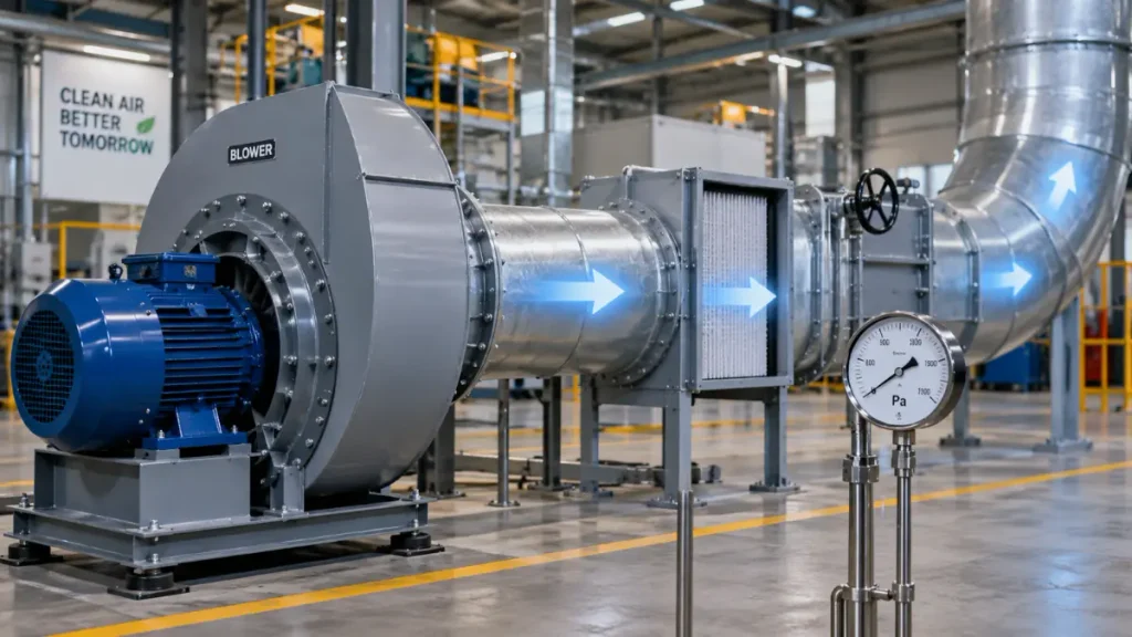
AMCA identifies fan affinity laws as relationships used to predict changes in airflow, pressure and power when operating conditions such as speed or density change.
Suppose a blower operates at:
Increase speed to: 1,800 RPM
Speed ratio:
So power increases by approximately: 72.8%
This demonstrates why simply increasing blower RPM can create a large motor-load increase.
Air temperature and altitude can affect blower performance. For approximate calculations:
Where:
Hot air has lower density than cold air at the same absolute pressure. This becomes particularly important for:
AMCA’s fan-performance standards include air-density effects when converting or comparing fan performance.
These terms are sometimes used interchangeably in factories, but they should not automatically be treated as identical.
A supplier may quote:
Before purchasing, ask:
Is the quoted pressure static pressure, total pressure, or pressure rise, and at what airflow and air density?
This one question can prevent an incorrect blower selection.
If the blower cannot overcome system resistance, you may experience:
The exact consequence depends on the application.
Oversizing can also create problems. Possible consequences include:
Therefore:
The goal is not maximum pressure. The goal is the required airflow at the required pressure with suitable efficiency and operating margin.
Static pressure can be measured using instruments such as:
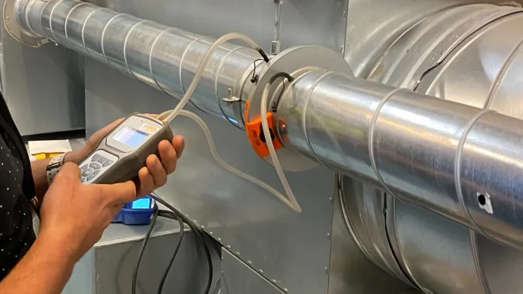
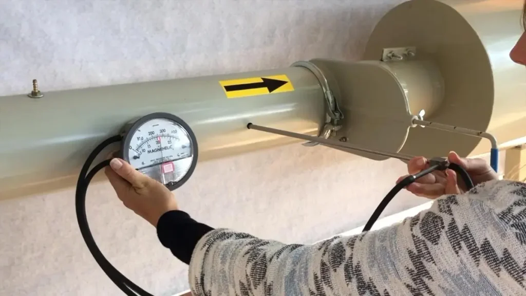
For industrial troubleshooting, measurement should be performed at appropriate locations, because pressure can change throughout the duct system.
For certified fan testing, standardized measurement procedures are used. ANSI/AMCA 210-25 establishes laboratory methods for determining airflow, pressure, power consumption, air density, speed and efficiency.
Use this 10-step method before buying an industrial blower.
Example: 15,000 m³/h
Example: 40°C
Example: 1,000 m above sea level
Include:
Do not blindly add a large percentage; the margin should reflect uncertainty in the design and process.
For example: 15,000 m³/h @ 1,800 Pa
Confirm the actual blower can deliver the required airflow at the required pressure.
Check:
| Parameter | Static Pressure | CFM |
|---|---|---|
| Meaning | Resistance/pressure capability | Air volume |
| Common U.S. unit | in. WG | CFM |
| Common SI unit | Pa/kPa | m³/s |
| Indian industry | mmWC | m³/h |
| Determines | Pressure capability | Air delivery |
| Used for | Overcoming resistance | Meeting process airflow |
| Selection | Must match system resistance | Must match process demand |
Both are required for proper blower selection.
| Air velocity | |
| Velocity pressure | |
| Total pressure | |
| Duct friction | |
| Fitting loss | |
| Air power | |
| Shaft power | |
| System pressure | |
| Fan speed-flow relationship | |
| Fan pressure relationship | |
| Fan power relationship | |
| U.S. approximate power equation |
Static pressure in a blower is one of the most important parameters for industrial blower selection. It tells you how much pressure the air-moving system requires and whether the blower can overcome the resistance created by ducts, elbows, filters, dampers, heat exchangers, burners, furnaces and other process equipment.
The most important principle is:
Never select an industrial blower using CFM alone. Select it using the required airflow + required pressure + operating conditions.
For example, instead of saying: “I need a 10,000 CFM blower,”
a much better engineering specification is: “I need 10,000 CFM at 6 in. WG static pressure, at 40°C air temperature.”
For Indian applications, you may express the same requirement using m³/h and mmWC: 16,990 m³/h at approximately 153 mmWC.
For U.S. applications, CFM and in. WG are commonly convenient units.
AMCA’s published fan-curve example demonstrates the same principle with a duty point of 12,000 CFM at 5.0 in. WG, while manufacturer ranges such as Atlas Copco’s published industrial blower data show how airflow, pressure and motor power must be considered together.
For a real factory purchase, the final blower should therefore be selected from the manufacturer’s performance curve or selection software, using the exact duty point, air density, temperature, elevation, pressure definition and efficiency. AMCA’s testing standards exist specifically to provide consistent methods for determining fan airflow, pressure, power, density, speed and efficiency.
Airflow tells you how much air you need.
Static pressure tells you how hard the blower must work to move that air through the system.
The correct blower is the one that delivers both at the required operating point efficiently.
Sources for further technical reference
Static pressure is the pressure component associated with the blower’s ability to overcome resistance in the connected air system. It is commonly expressed in Pa, kPa, mmWC or in. WG.
There is no single “good” static pressure. The correct pressure depends on the application’s airflow and system resistance.
CFM measures airflow volume, while static pressure represents pressure/resistance capability. A blower must provide the required combination of both.
Yes, depending on blower technology and design, but achieving both generally requires appropriate impeller design, speed, power and efficiency. The actual performance must be verified from the manufacturer’s curve.
Static pressure is important in HVAC because it measures the resistance airflow faces inside the ductwork, which directly affects your system’s efficiency, equipment lifespan, and indoor comfort,
To lower high static pressure in an HVAC system, you need to remove restrictions that block airflow and reduce the resistance the blower motor has to push against.
One ton of cooling capacity requires about 400 CFM (cubic feet per minute) of airflow in standard HVAC design.
For standard comfort cooling, 1 Ton of Refrigeration (TR) is roughly equal to 400 CFM (Cubic Feet per Minute) of airflow
1 cfm is equivalent to approximately 0.0025 tons of cooling capacity under standard conditions, meaning 2000 cfm is equal to approximately 5 tons of air conditioning.
The Noctua NF-A12x25 G2 is the best 120mm static pressure fan overall for its top-tier cooling performance and low noise levels.

Welcome! I am a dedicated entrepreneur running an industrial affiliate product website, helping businesses and professionals find the best tools, equipment, and resources for their needs. With a passion for industrial products and a keen eye for quality, I curate and recommend top-performing items that enhance efficiency and reliability.
Through my platform, I aim to simplify the buying process by providing valuable insights, expert reviews, and trusted affiliate links to high-quality industrial products. Whether you’re looking for the latest machinery, tools, or safety gear, I strive to connect you with the best solutions available.
Thank you for visiting, and I look forward to helping you make informed purchasing decisions!
