Our Location
Killa-Pardi, Dist. Valsad, 396125

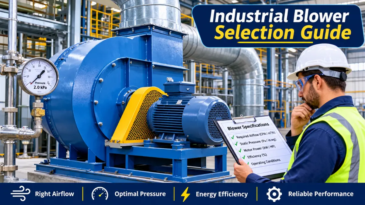
Right Industrial Blower Selection Guide explains nine critical factors for selecting an industrial blower, with technical formulas, practical calculations, application examples, and maintenance considerations.
Selecting the right industrial blower is important for maintaining airflow, controlling operating costs, improving production efficiency, and reducing equipment downtime. A blower that is too small may not provide the required airflow or pressure. An oversized blower may consume unnecessary electricity, increase noise, and create operational problems.
For industrial buyers in the United States and India, blower selection should be based on the actual application, required airflow, system resistance, air temperature, motor power, and operating conditions.
For example, a blower used for furnace combustion requires different performance characteristics from a blower used for dust collection, pneumatic conveying, machine cooling, or general ventilation.
The correct selection process starts with one important principle: choose a blower based on the required airflow and pressure at the actual operating point—not simply on motor horsepower or maximum advertised CFM.
Industrial blower selection is the process of identifying a blower that can deliver the required volume of air at the necessary pressure while meeting application, energy-efficiency, temperature, safety, and reliability requirements. The main selection parameters are:
A suitable blower must meet these requirements simultaneously.
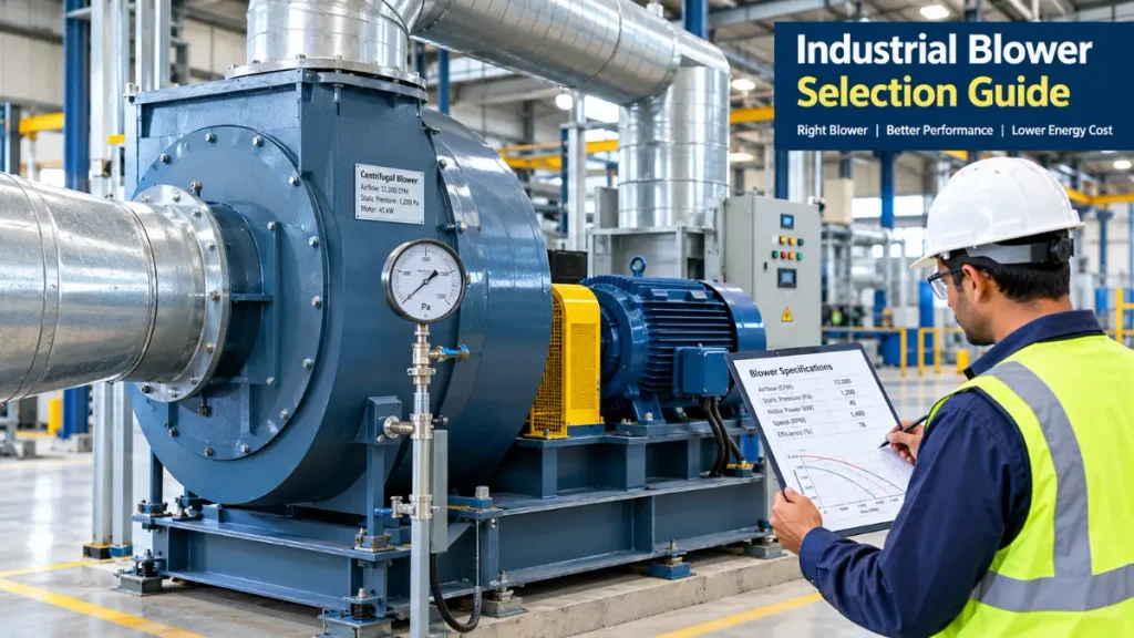
The first step is understanding what the blower must accomplish. Different applications require different airflow patterns, pressure capabilities, impeller designs, and construction materials.
| Application | Main requirement | Typical consideration |
|---|---|---|
| Furnace combustion | Stable combustion air | Temperature and pressure requirements |
| Dust collection | Airflow through filters and ducts | Filter resistance and dust characteristics |
| Industrial ventilation | Air exchange and heat removal | Air volume and duct losses |
| Pneumatic conveying | Moving materials through pipes | Conveying velocity and system pressure |
| Machine cooling | Removing heat from equipment | Airflow and temperature |
| Wastewater aeration | Supplying process air | Required pressure and process demand |
| Drying systems | Removing moisture | Air temperature, volume, and humidity |
| Packaging machinery | Process air supply | Pressure stability and duty cycle |
A manufacturing facility needs a blower to remove warm air from a production area. The engineer must calculate the required airflow and account for ductwork, bends, filters, louvers, and exhaust outlets.
A blower selected only by motor size may fail to provide the required ventilation once the complete system resistance is considered. In contrast, a furnace combustion blower may need a more carefully controlled pressure and airflow supply to maintain the required combustion conditions.
Selection tip: Define the process requirement before comparing brands or prices.
Airflow is one of the most important parameters in blower selection. It represents the volume of air delivered during a specified period. Common airflow units include:
Use these approximate conversions:
For example, a blower rated at 1,000 CFM provides approximately: 1,000 × 1.699 = 1,699 m³/h
Always confirm that the quoted airflow is available at the required operating pressure. Free-air or zero-pressure CFM may be much higher than the airflow delivered through an actual duct system.
For general room ventilation, an initial airflow estimate can be obtained from room volume and the required air changes per hour.
Formula: Required airflow (CFM) = Room volume (ft³) × ACH ÷ 60
Where ACH means air changes per hour. Consider a factory room measuring:
Room volume: 50 × 40 × 20 = 40,000 ft³
Required airflow: 40,000 × 6 ÷ 60 = 4,000 CFM
The initial ventilation estimate is therefore 4,000 CFM.
However, six air changes per hour is an illustrative assumption, not a universal industrial ventilation requirement. Actual airflow must be determined from heat loads, contaminants, occupancy, process emissions, applicable codes, and ventilation design requirements.
For hazardous dust, welding fumes, chemical vapours, or other process contaminants, general room air changes alone may not provide adequate control. A qualified ventilation engineer should calculate the required capture and exhaust airflow.
Additional airflow may be necessary when the application involves:
Do not add an arbitrary safety margin without reviewing the system design. Excessive oversizing can increase cost and energy consumption.
Airflow alone cannot determine the correct blower. The blower must also overcome the resistance created by the system.
Static pressure represents the pressure associated with overcoming resistance and moving air through the installation. The precise pressure definition used for equipment selection must match the manufacturer’s performance data. Common units include:
| Unit | Approximate conversion |
|---|---|
| 1 Pa | 1 N/m² |
| 1 kPa | 1,000 Pa |
| 1 in. w.g. | 249.1 Pa |
| 1 mm w.g. | 9.81 Pa |
Here, w.g. means water gauge.
System resistance can come from:
A dirty filter can substantially increase system resistance. The blower may continue running while delivering less airflow than the process requires.
Suppose an industrial air system has the following estimated losses:
| Component | Pressure loss |
|---|---|
| Straight ducts | 180 Pa |
| Elbows and fittings | 120 Pa |
| Air filter | 250 Pa |
| Heat exchanger | 150 Pa |
| Outlet and other components | 100 Pa |
| Total estimated system loss | 800 Pa |
Total pressure loss: 180 + 120 + 250 + 150 + 100 = 800 Pa
The blower must be selected to meet the required airflow at the calculated pressure, with an appropriate allowance for documented design uncertainty and expected filter loading.
In this example, 800 Pa is an illustrative system-loss estimate. The actual required fan static pressure or total pressure depends on the pressure reference points, inlet and outlet conditions, and system layout.
A blower that delivers 5,000 CFM at low resistance may deliver less airflow when connected to a restrictive duct network. Therefore, request the manufacturer’s performance curve and confirm that the required airflow and pressure can be achieved at the same operating point.
Different blower designs suit different pressure, airflow, and process requirements. The main types include centrifugal, axial, regenerative, and positive-displacement blowers.
A centrifugal blower uses a rotating impeller to accelerate air outward and convert velocity into pressure.
Common applications include:
Centrifugal blowers are available with different impeller designs. Backward-curved, forward-curved, and radial-blade designs have different pressure, efficiency, and material-handling characteristics.
The correct design depends on airflow, pressure, dust loading, particle characteristics, temperature, and the required operating range.
An axial blower moves air mainly parallel to its shaft.
Common applications include:
Axial blowers can provide high airflow, but their suitability depends on the pressure requirement and the selected fan’s performance curve.
A regenerative blower, also called a side-channel blower, repeatedly transfers energy to air through a rotating impeller and side-channel flow path.
Applications can include:
Its actual pressure capability and efficiency must be checked against the manufacturer’s operating limits.
Roots-type and other positive-displacement blowers move a defined volume of gas per rotation, subject to slip and operating conditions.
Applications include:
These machines can require specific protection against excessive differential pressure, including correctly designed relief and control arrangements.
| Blower type | Main selection consideration | Example application |
|---|---|---|
| Centrifugal | Pressure, efficiency, impeller design | Dust collection |
| Axial | High airflow and system resistance | Ventilation |
| Regenerative | Flow-pressure operating envelope | Packaging equipment |
| Positive displacement | Required flow and differential pressure | Pneumatic conveying |
No blower type is automatically best for every application. Compare actual performance curves and operating limits before making a decision.
Motor power is another critical selection factor. The motor must supply enough power to operate the blower at the required airflow and pressure.
Two common units are:
The conversion is: 1 HP = 0.746 kW
Therefore:
kW = HP × 0.746
HP = kW ÷ 0.746
These conversions relate the power units. They do not establish the blower’s actual electricity consumption.
For a preliminary estimate of the power transferred to the air, use:
Air power (W) = Airflow (m³/s) × Pressure rise (Pa)
This is a simplified relationship. For a real blower, pressure definition and density effects must be considered consistently.
The required shaft power is higher than air power because of aerodynamic and mechanical losses. Electrical input is higher again because of motor and drive losses.
A practical preliminary relationship is: Electrical input power ≈ Air power ÷ Overall efficiency
Use an appropriate overall efficiency based on the blower, motor, and drive at the intended operating point. Do not assume that a generic efficiency figure applies to every blower.
Assume the design requires:
First, convert airflow to cubic metres per second.
5,000 CFM × 0.0004719 = approximately 2.36 m³/s
Calculate air power:
2.36 × 1,500 = 3,540 W, or 3.54 kW
Estimate electrical input:
3.54 ÷ 0.60 = 5.90 kW
The estimated electrical input is approximately 5.9 kW under these assumptions.
This is a preliminary calculation, not a final motor-selection rating. The engineer must check the manufacturer’s power curve, maximum absorbed power, operating range, starting requirements, altitude, air density, drive losses, and applicable service conditions before selecting the motor.
Two blowers with identical motor ratings can produce different airflow and pressure because of differences in impeller geometry, speed, efficiency, and system resistance.
Select the blower first using the required operating duty point, then verify that the motor and drive are suitable for the full operating envelope.
Temperature and air density can affect blower performance, power requirements, material selection, and equipment life. A blower handling ordinary room air may not be suitable for a furnace exhaust or a hot industrial drying process.
Check the following before purchasing:
For high-temperature applications, the manufacturer may require a special impeller, casing material, shaft arrangement, bearing location, cooling arrangement, or thermal expansion allowance.
Air density decreases as temperature increases at constant absolute pressure. For an ideal gas, density is approximately proportional to absolute pressure and inversely proportional to absolute temperature.
At constant pressure: ρ₂ = ρ₁ × (T₁ ÷ T₂)
Temperatures must be expressed in kelvin.
For example, assume air density is 1.20 kg/m³ at 20°C. At 100°C, assuming the same absolute pressure:
T₁ = 293.15 K
T₂ = 373.15 K
ρ₂ = 1.20 × (293.15 ÷ 373.15)
ρ₂ ≈ 0.94 kg/m³
The air density is approximately 0.94 kg/m³ under these assumptions.
This example illustrates the effect of temperature on density. Actual blower performance also depends on the machine’s operating conditions, gas composition, pressure, speed, and mechanical limits.
Industrial buyers should also consider:
For combustible dust or flammable gas applications, do not rely on a standard industrial motor or ordinary blower construction. A qualified engineer must assess the hazard and specify equipment suitable for the applicable classification and local regulations.
A blower’s purchase price is only one part of its lifetime cost. Electricity, maintenance, replacement parts, and production downtime can contribute significantly to the total cost of ownership.
This is especially important in factories where blowers operate for long hours.
Use the following formula:
Annual energy (kWh) = Average electrical input (kW) × Annual operating hours
Suppose a blower has an average measured electrical input of 15 kW and operates for 16 hours per day for 300 days per year.
Annual operating hours: 16 × 300 = 4,800 hours
Annual electricity consumption: 15 × 4,800 = 72,000 kWh
If the illustrative electricity rate is ₹8/kWh: 72,000 × ₹8 = ₹576,000 per year
The estimated annual energy cost is ₹5.76 lakh.
At an illustrative U.S. electricity rate of $0.12/kWh, the same energy use would cost:
72,000 × $0.12 = $8,640 per year
These are examples, not current electricity-price quotations. Actual costs depend on the utility tariff, demand charges, taxes, time-of-use rates, and measured energy consumption.
Assume two candidate blowers deliver the same required duty:
| Parameter | Blower A | Blower B |
|---|---|---|
| Average electrical input | 15 kW | 12 kW |
| Annual operating hours | 4,800 | 4,800 |
| Annual energy use | 72,000 kWh | 57,600 kWh |
| Cost at ₹8/kWh | ₹576,000 | ₹460,800 |
Potential annual energy-cost difference: ₹576,000 − ₹460,800 = ₹115,200
Blower B could save ₹1.152 lakh per year under these assumptions, provided both options meet the same airflow, pressure, reliability, and process requirements.
This comparison demonstrates why energy efficiency matters. Actual savings must be confirmed from manufacturer data and operating measurements.
A blower typically has a preferred operating region near its best efficiency point (BEP). Operating far from that region can reduce efficiency and may increase noise, vibration, or mechanical stress, depending on the design.
For variable airflow requirements, a variable-frequency drive (VFD) can be useful. It changes motor speed to match process demand.
However, savings depend on the blower type, system curve, motor and drive efficiency, minimum operating speed, and process requirements. Do not assume that every VFD installation produces the same percentage of energy savings.
The U.S. Department of Energy’s Better Plants program recommends measures such as operating close to the best efficiency point, improving inlet and outlet airflow conditions, and considering speed control for variable-load fan systems.
The blower performance curve is one of the most important documents to review before purchasing equipment.
It shows how the blower performs under different operating conditions, typically including airflow, pressure, and power. Depending on the manufacturer, efficiency, speed, and other information may also be included.
A performance curve helps engineers determine whether a particular blower can deliver the required airflow at the system’s operating pressure. The actual operating point is determined by the intersection of the blower performance curve and the system resistance curve.
As resistance increases, the operating point changes. A blower may then deliver less airflow than expected.
1. Airflow versus pressure curve
Shows the pressure available at different airflow rates.
2. Power curve
Shows how power demand changes as airflow or operating conditions change.
3. Efficiency curve
Identifies the operating region where the blower converts input power into useful air power most effectively.
4. Speed curves
Help compare performance at different rotational speeds, when provided.
Suppose a factory needs:
A manufacturer’s curve must confirm that the selected blower delivers 5,000 CFM at 1,500 Pa at the proposed operating speed. It is not sufficient for the datasheet to show a maximum airflow of 5,000 CFM at zero or very low pressure. That point may not represent the actual installation duty.
The selected operating point should also be checked for efficiency, absorbed power, stability, noise, and allowable operating limits.
A blower’s published performance may be affected by poor inlet conditions, abrupt duct transitions, elbows close to the inlet or outlet, and other installation effects.
The Air Movement and Control Association International (AMCA) explains that installation-related system effects can reduce field performance and increase energy use, noise, vibration, and mechanical stress.
For reliable performance:
A correctly sized blower must also operate reliably in the actual industrial environment.
Maintenance requirements influence operating cost, availability, and equipment life. Before purchasing, review the expected maintenance schedule and availability of replacement components.
Bearings: Confirm bearing type, lubrication method, operating-temperature limits, and replacement requirements.
Impeller: Check the suitability of the impeller material and design for dust, erosion, corrosion, and process conditions.
Motor: Verify voltage, frequency, phase, enclosure, insulation, cooling, and suitability for the installation environment.
Drive system: Review direct-drive or belt-drive requirements, alignment, belt tension, and maintenance access.
Vibration: Confirm the manufacturer’s vibration limits and the monitoring requirements for critical applications.
Noise: Check the expected sound level and whether silencers, acoustic enclosures, or other controls are required.
Spare parts: Check availability of bearings, seals, belts, filters, and other service items.
Equipment requirements depend on the application and jurisdiction. A blower installed in an ordinary ventilation system may have different compliance requirements from equipment used in combustible dust handling, chemical processing, or a hazardous atmosphere.
For U.S. projects, check applicable OSHA requirements, electrical codes, local building and fire codes, and relevant equipment standards. For projects in India, verify applicable BIS standards, electrical safety requirements, factory rules, fire requirements, and local statutory obligations.
Where applicable, ask suppliers for relevant performance test reports, certification details, and documented operating limits. AMCA-certified ratings may help verify fan performance when the specific product and rating fall within the relevant certification scope.
Do not assume that every blower requires the same certification or that a certification automatically establishes suitability for every hazardous process.
Use this checklist before requesting a quotation.
Consider a manufacturing facility in India or the United States that needs a blower for a process-air application. The following requirements are illustrative and are not a recommendation for a specific machine.
| Design parameter | Example requirement |
|---|---|
| Application | Industrial process air |
| Required airflow | 5,000 CFM |
| Required pressure rise | 1,500 Pa |
| Air temperature | 20–40°C |
| Operating schedule | 16 hours/day |
| Operating days | 300 days/year |
| Annual operating time | 4,800 hours |
| Electrical supply | To be confirmed on site |
| Blower type | Selected using performance requirements |
| Control method | Fixed speed or VFD, depending on demand |
5,000 CFM × 0.0004719 = approximately 2.36 m³/s.
Air power = airflow × pressure rise
2.36 × 1,500 = approximately 3.54 kW.
If assumed overall efficiency is 60%:
3.54 ÷ 0.60 = approximately 5.90 kW.
This provides an initial estimate for comparison. The manufacturer’s selection software and technical data must confirm the required operating point and actual power demand.
At a measured average input of 5.90 kW:
5.90 × 4,800 = 28,320 kWh/year.
At an illustrative electricity rate of ₹8/kWh, annual energy cost would be:
28,320 × ₹8 = ₹226,560.
Actual energy use and costs will vary with operating conditions and the selected equipment.
Before placing an order, confirm that the selected blower can deliver 5,000 CFM at 1,500 Pa with acceptable efficiency and power demand. Check the motor, drive, installation layout, temperature limits, and operating envelope.
This example demonstrates the selection method. Final equipment sizing requires verified system calculations and manufacturer performance data.
| Mistake | What Happened | Solution |
| Selecting by horsepower alone | Motor HP does not tell you how much airflow a blower will provide at a given pressure. | Select using the required duty point and verify the power curve. |
| Ignoring static pressure | A blower may provide high free-air flow but insufficient airflow through restrictive ducts and filters. | Calculate system resistance and check the performance curve. |
| Oversizing the blower | Oversizing can increase purchase cost, power consumption, noise, and control difficulties. | Use realistic operating requirements and account for documented design uncertainty. |
| Ignoring air temperature | Hot air has a different density from cool air and may require different materials and mechanical arrangements. | Specify normal and maximum operating temperatures. |
| Ignoring filter loading | As a filter becomes dirty, its pressure drop may increase and airflow may decrease. | Include clean and expected loaded-filter conditions in the system design. |
| Choosing only by initial price | A cheaper blower may consume more electricity or require more maintenance over its service life. | Compare purchase price, energy use, maintenance, reliability, and downtime. |
| Ignoring installation effects | Poor inlet conditions and restrictive duct transitions can reduce actual performance. | Follow installation guidance and verify performance after commissioning. |
For your factory, we can calculate the room volume, estimate the ventilation airflow, and develop a preliminary industrial blower specification. The final blower selection depends on whether you need general ventilation, heat removal, dust extraction, or furnace combustion air.
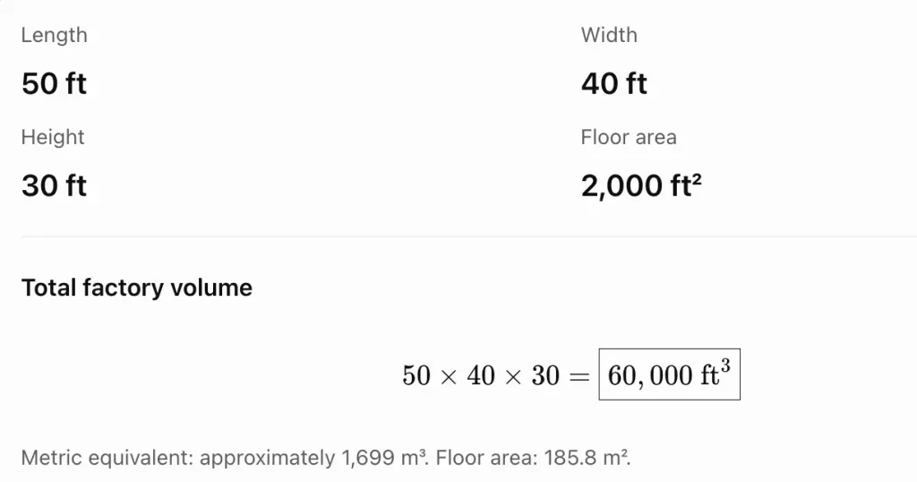
1. Your factory dimensions
2. Calculate the required blower airflow
For a preliminary estimate of general factory ventilation, use the air changes per hour (ACH) method.
Formula:
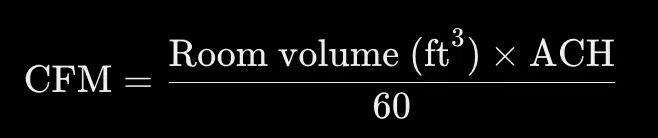
Your factory volume is 60,000 ft³.
| Assumed air changes | Airflow calculation | Required airflow |
|---|---|---|
| 4 ACH | 60,000 × 4 ÷ 60 | 4,000 CFM |
| 6 ACH | 60,000 × 6 ÷ 60 | 6,000 CFM |
| 8 ACH | 60,000 × 8 ÷ 60 | 8,000 CFM |
| 10 ACH | 60,000 × 10 ÷ 60 | 10,000 CFM |
These are preliminary scenarios, not mandatory ventilation rates. The correct rate depends on the factory process, heat generation, pollutants, occupancy, and applicable ventilation requirements.
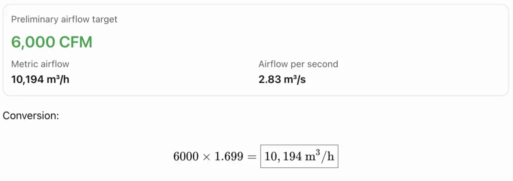
For the initial example, let’s use 6,000 CFM as a planning target for general ventilation.
3. Which type of industrial blower should you select?
For a factory requiring ordinary heat removal and fresh-air circulation, these are the main options.
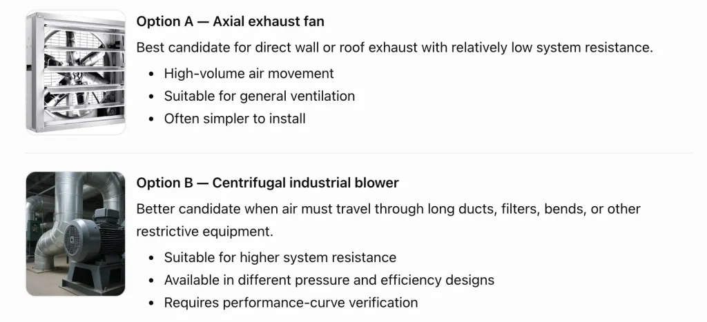
My preliminary recommendation: If your purpose is general ventilation and you can exhaust directly through factory walls or the roof, start by evaluating industrial axial exhaust fans. If your system uses long ductwork, filters, or process equipment, evaluate a centrifugal blower instead.
For general ventilation, you may need both exhaust and make-up air. An exhaust fan cannot work effectively if replacement air cannot enter the building.
4. Practical calculation for motor power
Airflow alone is not enough to select the motor. We also need the required pressure.
For an illustrative calculation, assume:
These are calculation assumptions, not confirmed specifications for your factory.
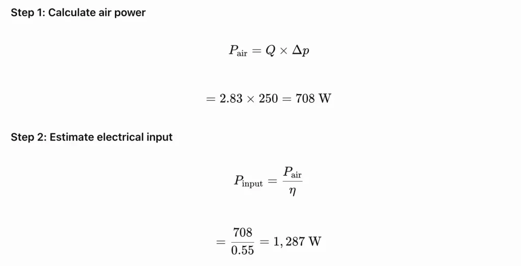
Estimated electrical input = 1.29 kW under these assumptions.
The final motor rating must be selected using the manufacturer’s fan curve, absorbed-power data, operating limits, and appropriate motor sizing. Do not purchase a motor based on this preliminary calculation alone.
5. Preliminary technical specification
For requesting a quotation from blower manufacturers, use the following as a starting specification for general ventilation.
| Parameter | Preliminary requirement |
|---|---|
| Application | General factory ventilation |
| Factory volume | 60,000 ft³ / 1,699 m³ |
| Planning airflow | 6,000 CFM / 10,194 m³/h |
| Blower type | Axial exhaust fan for low-resistance exhaust; centrifugal for higher resistance |
| Required pressure | To be calculated from the actual installation |
| Motor rating | Manufacturer to select after confirming the duty point |
| Air temperature | Measure normal and maximum factory temperature |
| Electrical supply | Confirm site voltage, phase and frequency |
| Installation | Wall, roof or duct-mounted, as applicable |
| Construction | Suitable for actual dust, moisture and corrosion exposure |
| Safety | Guards, electrical protection and applicable local compliance |
| Documentation | Performance curve, power data, dimensions and installation instructions |
Important: Do not accept a free-air CFM rating alone
Ask the supplier to confirm that the fan can deliver 6,000 CFM at the required static pressure. A fan advertised as 6,000 CFM may deliver less once installed in a restrictive duct system.
6. What information is still needed for accurate selection?
The airflow calculation gives us a starting point, but I would not finalize the blower or motor HP until these details are confirmed.
Tell me how your factory operates so I can refine the blower type, airflow, pressure and motor specification.
My current conclusion:
For your 50 × 40 × 30 ft factory, 6,000 CFM is a reasonable example for preliminary general-ventilation planning, using an assumed six air changes per hour. It is not yet a final engineering requirement. Once the application and pressure requirements are known, the blower type, exact CFM, static pressure, motor kW/HP, and number of fans can be selected more reliably.
Choosing the right industrial blower requires more than comparing CFM ratings, motor horsepower, or purchase prices. A reliable selection considers the application, airflow, static pressure, blower type, motor power, temperature, efficiency, performance curve, and maintenance requirements.
For buyers in the USA and India, the best approach is to define the operating requirements, calculate the system resistance, compare documented manufacturer performance data, and evaluate lifetime operating costs.
The most important rule is simple: select an industrial blower that delivers the required airflow at the required pressure, within its recommended operating range and with acceptable energy consumption.
Before purchasing, request a technical datasheet, performance curve, absorbed-power data, installation requirements, and a quotation based on the specified duty point.
References and Further Reading:
AMCA International — Straightening Out Fan Curves: https://www.amca.org/educate/articles-and-technical-papers/amca-inmotion-articles/straightening-out-fan-curves.html
AMCA International — Mitigating System Effect to Optimize Fan Performance and Efficiency: https://www.amca.org/educate/articles-and-technical-papers/amca-inmotion-articles/mitigating-system-effect-to-optimize-fan-performance-efficiency.html
U.S. Department of Energy — Fans and Blowers: https://www.energy.gov/cmei/buildings/fans-and-blowers
U.S. Department of Energy, Better Plants — Fan System Energy Performance: https://betterbuildingssolutioncenter.energy.gov/better-plants/fans
AMCA International — Fan Energy Index (FEI): https://www.amca.org/advocate/energy-efficiency-and-system-performance/about-fan-energy-index/
Technical note: The numerical examples in this article are illustrative calculations, not certified blower-selection results. Confirm final airflow, pressure, power, efficiency, and operating limits with the manufacturer’s engineering data.
Define the application, calculate the required airflow and system pressure, choose a suitable blower type, and verify the manufacturer’s performance curve. Also evaluate motor power, efficiency, temperature, reliability, and safety.
The required airflow and pressure at the actual operating point are two of the most important factors. Both must be satisfied simultaneously.
For preliminary room ventilation, use:
CFM = Room volume in ft³ × required ACH ÷ 60.
For duct systems, process equipment, and local exhaust, airflow should be determined from the process requirements and appropriate engineering calculations.
CFM measures volumetric airflow. Static pressure describes a pressure component associated with the air system and its resistance. A blower must provide the required airflow at the required pressure.
Neither is universally better. Centrifugal blowers are commonly used where the system requires a suitable combination of airflow and pressure. Axial blowers are often useful for high-volume ventilation. Final selection depends on the actual performance curve and application.
A preliminary estimate uses air power divided by overall efficiency:
Electrical input power ≈ (Airflow × Pressure rise) ÷ Overall efficiency.
Use consistent SI units and verify the result against the manufacturer’s power curve and motor requirements.
No. Higher horsepower does not guarantee the correct airflow, pressure, or efficiency. An oversized blower may waste energy and create operating problems.
The best efficiency point is the operating condition where the blower reaches its maximum efficiency for the relevant performance curve. Operating close to this region is often beneficial, provided the required process conditions are met.
Yes, a variable-frequency drive can reduce power consumption when the process requires variable airflow and the blower-system combination benefits from speed control. Actual savings depend on the system curve, blower characteristics, drive losses, and operating schedule.
Provide the application, required airflow, pressure definition and value, operating temperature, gas composition, site conditions, operating hours, electrical supply, control requirements, and applicable safety requirements.
Determine the required capture airflow, duct transport conditions, filter pressure drop, dust characteristics, and any combustible-dust hazards. The blower must meet the design airflow at the total system resistance.
Maintenance frequency depends on operating hours, dust exposure, temperature, bearing arrangement, manufacturer instructions, and criticality. Use a documented inspection schedule and monitor vibration, temperature, noise, lubrication, and airflow.
Yes. Lower atmospheric pressure at higher altitude generally reduces air density. This can affect mass flow, pressure development, motor cooling, and system performance. The manufacturer should evaluate the actual site conditions.
Review applicable local regulations and relevant performance standards. AMCA publications and certification programs can help with fan performance evaluation where applicable. The correct requirements depend on equipment type, installation, and process hazards.
Start by measuring actual airflow, pressure, and electrical input. Maintain clean filters, minimize unnecessary system resistance, correct installation problems, and evaluate efficient equipment or VFD control where appropriate.

Welcome! I am a dedicated entrepreneur running an industrial affiliate product website, helping businesses and professionals find the best tools, equipment, and resources for their needs. With a passion for industrial products and a keen eye for quality, I curate and recommend top-performing items that enhance efficiency and reliability.
Through my platform, I aim to simplify the buying process by providing valuable insights, expert reviews, and trusted affiliate links to high-quality industrial products. Whether you’re looking for the latest machinery, tools, or safety gear, I strive to connect you with the best solutions available.
Thank you for visiting, and I look forward to helping you make informed purchasing decisions!
